Cards System Summary
Introduction

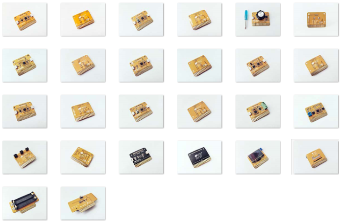
'Longan Cards' is a unique open source development platform developed by Longan Labs. As a plug and play development platform, Longan cards allow you to quicky build wide array of prototypes and applications in no time. A full set of Arduino libraries and plenty of example codes are available to play with Longan cards platform.
NOTE: Most of the Longan cards are based on the I2C communication protocol.
Longan cards fall into following categories:
- Sensor
- Actuator
- Controller
- Display
- Communication
- Support
You can use Longan Cards with following Longan boards.
- Game board
- Extension board
- Car board
- Sensor board
- Pi Hap
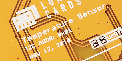
All cards that support I2C communication protocol comes with a unique factory default I2C address can be found on the back of the card.

Cards and Boards
Following table presents the type, I2C address, and communication protocol of each Longan card.
| SKU | Name | Type | I2C address | Coomunication Protocol |
|---|---|---|---|---|
| 1011001 | Temperature Card | Sensor | 0x01 | I2C |
| 1011002 | Sound Sensor Card | Sensor | 0x02 | ADC |
| 1011003 | PIR Sensor Card | Sensor | 0x03 | I/O |
| 1011004 | Gesture Sensor Card | Sensor | 0x04 | I2C |
| 1011007 | Rotary Angle Card | Sensor | 0x07 | ADC |
| 1011008 | BME280 Card | Sensor | 0x08 | I2C |
| 1011010 | Light Sensor Card | Sensor | 0x0A | ADC |
| 1011012 | RTC Card | Sensor | 0x0C | I2C |
| 1011021 | 9-Dof Sensor Card | Sensor | 0x15 | I2C |
| 1011027 | Button Input Card | Sensor | 0x1B | I/O |
| 1011028 | VOC&eCO2 Gas Sensor | Sensor | 0x1C | I2C |
| 1011029 | IR Recever Card | Sensor | 0x1D | 其他协议 (Other) |
| 1011032 | Line Finder Card | Sensor | 0x1E | 其他协议 (Other) |
| 1012001 | Relay Card | Actuator | 0x41 | I/O |
| 1012002 | Buzzer Card | Actuator | 0x42 | I/O |
| 1012003 | Motor Driver Card | Actuator | 0x43 | I/O |
| 1013001 | Carduino 328 | Controller | - | |
| 1013007 | Carduino 32U4 | Controller | - | |
| 1014001 | OLED Card | Display | - | SPI |
| 1015003 | IR Emitter Card | Communication | 0x44 | 其他协议 (Other) |
| 1016006 | Programmer Card | Support | - | |
| 1016007 | AAA Battery Card | Support | - | |
| 1017002 | Extension Board | Board | - | |
| 1017006 | PI Hap for Longan Card | Board | - | |
| 1017007 | Sensor Display | Board | - | |
| 1017008 | Game | Board | - | |
| 1017009 | Car Board | Board | - |
Pins
The edge connector (gold fingers) has total of 30 contacts (each side has 15 contacts).
On the front side of the temperature card, a white arrow is printed near the edge connector indicates the pin #1. You can find some pin numbers printed on the edge connector itself (1, 15, and 29). You can count the pin numbers starting with 1 and count by twos from right to left would be 1, 3, 7, 9, 11, 15, 17, 19, 21, 23, 27, and 29. Notice that all the counts are odd numbers.
On the back side of the temperature card, you also can find some pin numbers printed on the edge connector itself (2, 16, and 30). You can count the pin numbers starting with 2 and count by twos from left to right would be 2, 4, 6, 8, 10, 12, 14, 16, 18, 20, 22, 24, 26, 28 and 30. Notice that all the counts are even numbers.
The gold fingers of each Longan card exposes all or subset of pins shown in the following figure.

GPIO Pins
This is the general purpose I/O pin set for the Carduino. GPIO consists of digital, analog, I2C, SPI, and UART pins. Most pins can do PWM output. Also, all pins can be used as interrupt pins.
- Digital (Front: pin #9, #11, #21 / Back: pin #10, #12, #22)
- Analog (Front: pin #13, #19 / Back: pin #14, #20)
NOTE: Motor driver card uses analog pins to drive two motors.
I2C Pins
Following pins can be used for I2C communication.
- SDA: Digital I/O, I2C bus serial bidirectional data line (Front: pin #5, #25 / Back: pin #6, #26)
- SCL: Digital Input, I2C bus serial clock input (Front: pin #7, #23 / Back: pin #8, #24)
Power Pins
Following pins connect with the common power bus of the board.
- VCC: Power supply (Front: pin #1, #29 / Back: pin #2, #30)
- GND: To be connected to the system ground (Front: pin #3, #27 / Back: pin #4, #28)
Hardware SPI Pins
These are the hardware SPI pins that can be used to communicate with high speed.
- SCK – Serial Clock (Front: pin #17)
- MISO - Master In Slave Out, takes data from the Carduino to the SPI device (Front: pin #15)
- MOSI – Master Out Slave In, takes data to the Carduino from the SPI device (Back: pin #16)
Hardware UART / Serial Pins
These pins can be used to connect devices support with UART using two wires.
- TX – Transmits data, connects with Carduino RX (Back: pin #22)
- RX – Receives data, connects with Carduino TX (Front: pin #21)
NOTE: The pin functions of Carduino is exactly same with the pin functions of Arduino Leonardo.
How to Use
A card can be plugged into an edge connector slot of one of the following Longan boards.
- Game board
- Car board
- Sensor board
- Extension board
- Pi Hap
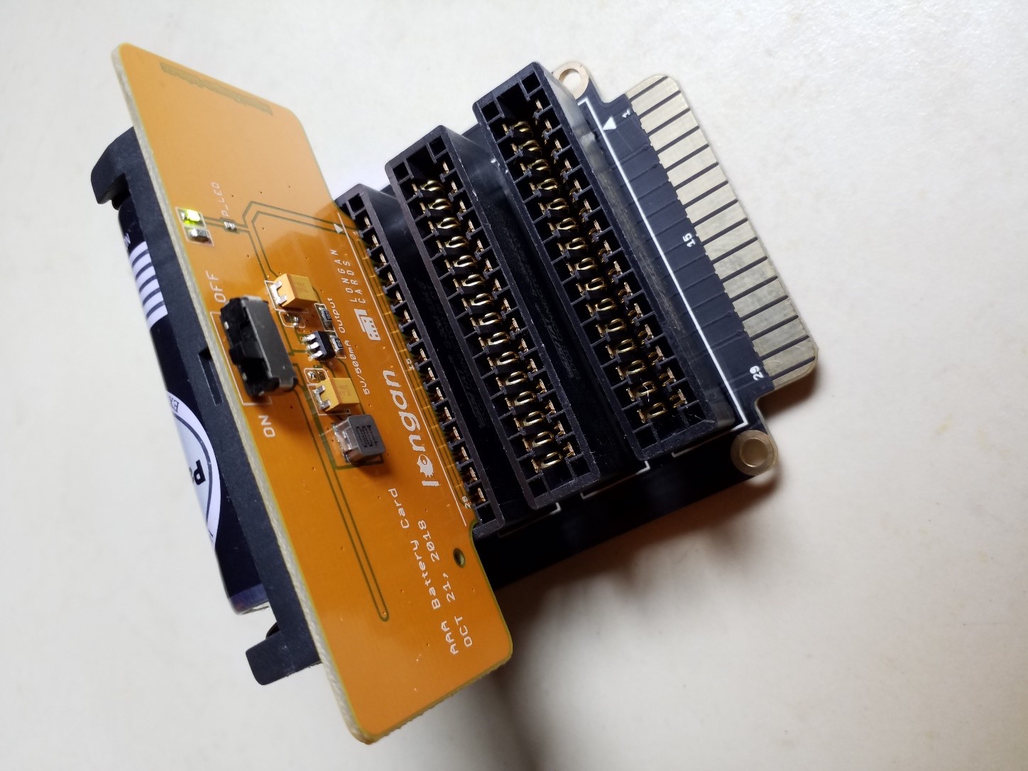
When you plugging, the white arrow head printed on the card should be pointing toward the white arrow head printed near the edge connector slot of the board. Once plugged, it can communicate with the Carduino through the I2C bus line of the board. It will also connect to the common power bus of the board.

I2C in Depth
Some of the Longan cards (all sensor, actuator, and communication cards) use I2C interface to communicate with the Carduino. They use I2C for read/write data and share the same I2C register. This allows you to use a single code to read data from all the sensor cards. Following table presents the typical I2C register map of a Longan card.
| Address | Name | Type | Reset Value | Lenght (Byte) | Description |
|---|---|---|---|---|---|
| 0x01 | DEVID | R | \ | 1 | Device ID |
| 0x02 | SENSOR_CNT | R | \ | 1 | Number of sensors on the card |
| 0x03 | SEN_NAME_LENGTH | R | \ | 1 | Length of the name |
| 0x04 | ADDR | R/W | \ | 1 | Device I2C address |
| 0x10 | NAME | R | \ | MAX 20 | Device name |
| 0x11 | SKU | R | \ | 4 | Device SKU |
| 0x12 | VERSION | R | \ | 4 | Version |
| 0x30 | VALUE_0 | R | \ | 6 | Sensor 0 |
| ... | |||||
| 0X35 | VALUE_5 | R | \ | 4 | Sensor 5 |
| ... |
Register Definitions
Register 0x01 – DEVID (Read Only)
Card ID.
Return: 1 byte
Register 0x02 - SENSOR_CNT (Read Only)
Number of sensors on the board. As an example, the BME280 card has 4 sensors: temperature, humidity, pressure and altitude. Therefore the SENSOR_CNT value for BME280 card is 4.
Return: 1 byte
Register 0x03 - SEN_NAME_LEN(Read Only)
Length of the card name.
Return: 1 byte
Register 0x04 – ADDR (Read/Write)
I2C Address of the card.
Return: 1 byte
Write: 1 byte
Register 0x10 – NAME (Read Only)
Name of the card as a string, max 20 bytes.
Return 1~20 byte(s)
Register 0x11 – SKU (Read Only)
SKU of the card
Return: 4 bytes
Register 0x12 – VERSION (Read Only)
Version
Return: 4 bytes
Register 0x30-0x3F: VALUE_n
Sensor value
Return: 6 bytes, define as below:
| 1 | 2 | 3 | 4 | 5 | 6 |
|---|---|---|---|---|---|
| DTA_TYPE | VAL0 | VAL1 | VAL2 | VAL3 | UNIT |
DTA_TYPE:
Float: TYPE_FLOAT
Int: DTA_TYPE_INT