9-Dof Sensor Card
Introduction
9-Dof Sensor Card is a high performance 9-axis motion tracking card from Longan Labs, which is based on MPU-9250. The MPU-9250 provides,
- 3-Axis gyroscope
- 3-Axis accelerometer
- 3-Axis magnetometer
Hence, the MPU-9250 is a 9-axis Motion Tracking device that combines a 3-axis gyroscope, 3-axis accelerometer, 3-axis magnetometer and a Digital Motion Processor™ (DMP).
Features
-
Gyroscope Features
- Digital-output X-, Y-, and Z-Axis angular rate sensors (gyroscopes) with a user-programmable fullscale range of ±250, ±500, ±1000, and ±2000°/sec and integrated 16-bit ADCs.
-
Accelerometer Features
- Digital-output triple-axis accelerometer with a programmable full scale range of ±2g, ±4g, ±8g and ±16g and integrated 16-bit ADCs.
-
Magnetometer Features
- 3-axis silicon monolithic Hall-effect magnetic sensor with magnetic concentrator.
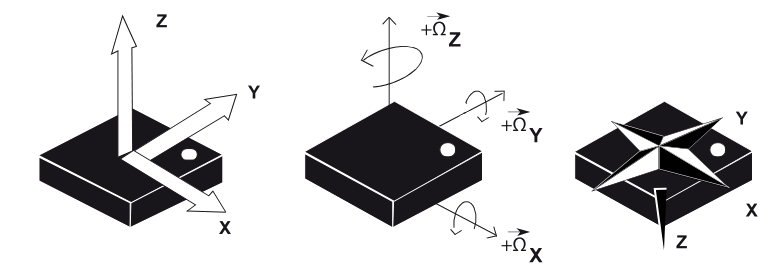
The following figure shows the axes of accelerometer, gyroscope, and compass, respectively.
Specifications
- Supports two wire I2C bus interface
- Two 4 pin SH1.0 connectors -allows you to connect MCUs or cards which support I2C communication protocol with dupont cables.
- 30 pin gold fingers
- MPU-9250 9-axis motion tracking device
- ATmega 168PA microprocessor - runs card firmware.
- LED indicator – flashes when Carduino read/write data from/to the card through I2C.
- Operating Voltage: 5V
- Digital-output 3-Axis angular rate sensors (gyroscopes) with a user-programmable full-scale range of ±250, ±500, ±1000, and ±2000°/sec
- Digital-output 3-Axis accelerometer with a programmable full scale range of ±2g, ±4g, ±8g and ±16g
- Digital-output 3-Axis accelerometer with a full scale measurement range is ±4800μT
I2C Address
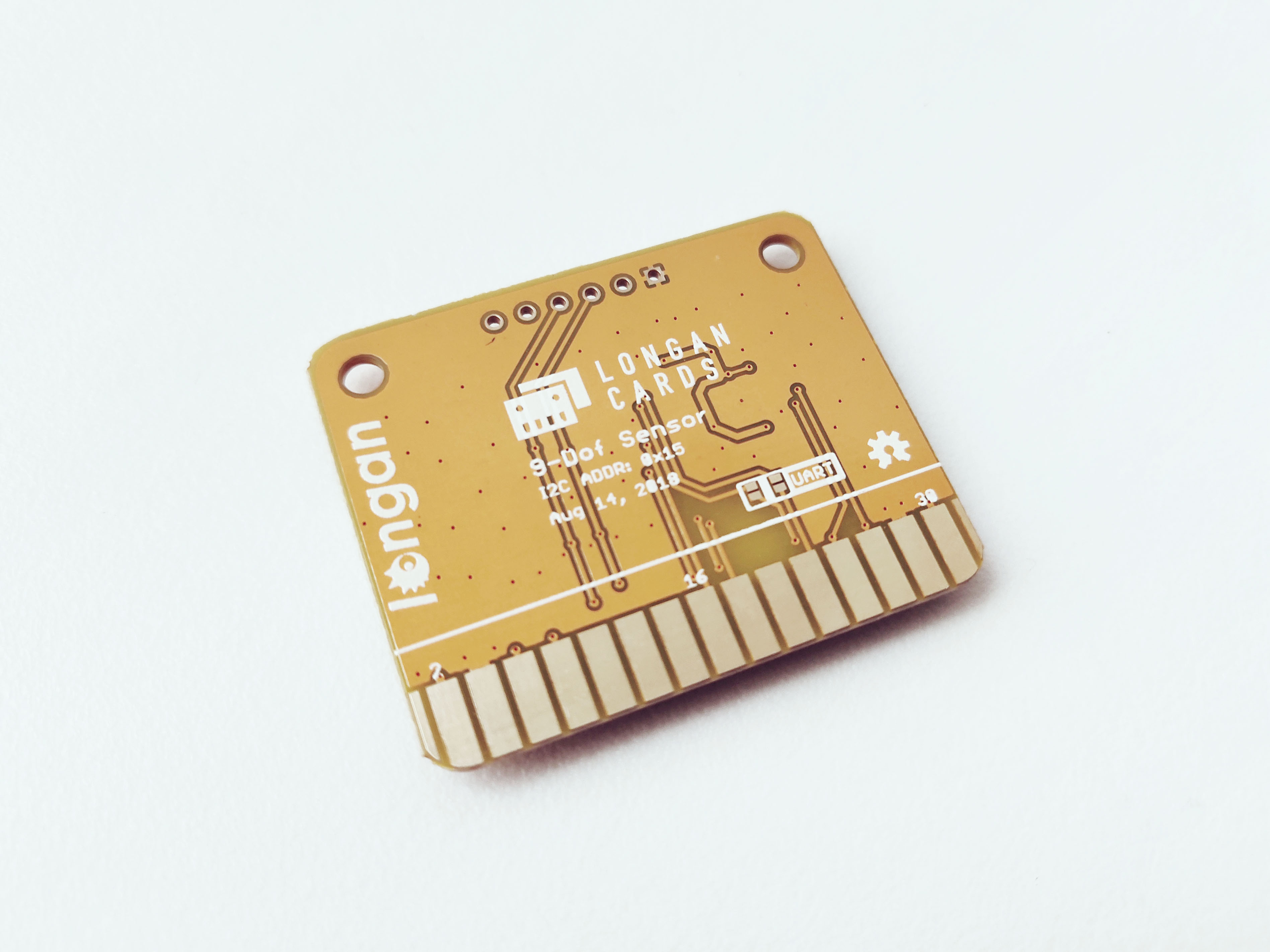
The default I2C address is printed on the back side of the card which is 0x15. However, you can change it to a different address with the card firmware (Read our wiki for how to change the default I2C address of a card.).
Pins
The edge connector (gold fingers) has total of 30 contacts (each side has 15 contacts).
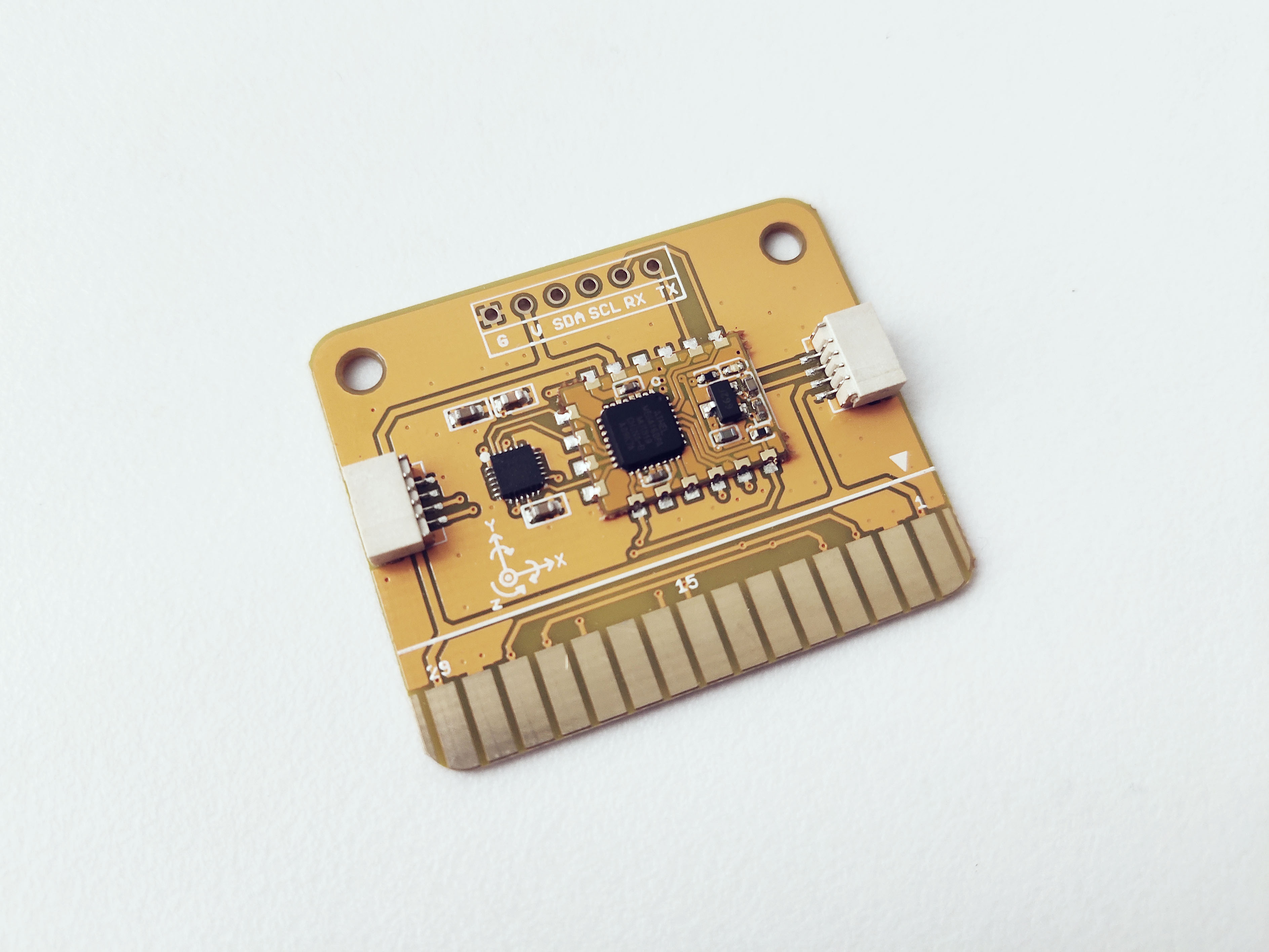
On the front side of the 9-Dof Sensor Card, a white arrow is printed near the edge connector indicates the pin #1. You can find some pin numbers printed on the edge connector itself (1, 15, and 29). You can count the pin numbers starting with 1 and count by twos from right to left would be 1, 3, 7, 9, 11, 15, 17, 19, 21, 23, 27, and 29. Notice that all the counts are odd numbers.
On the back side of the 9-Dof Sensor Card, you also can find some pin numbers printed on the edge connector itself (2, 16, and 30). You can count the pin numbers starting with 2 and count by twos from left to right would be 2, 4, 6, 8, 10, 12, 14, 16, 18, 20, 22, 24, 26, 28 and 30. Notice that all the counts are even numbers.
Among the 30 pins, following pins can be used for I2C communication.
- SDA: Digital I/O, I2C bus serial bidirectional data line (Front: pin #5, #25 / Back: pin #6, #26)
- SCL: Digital Input, I2C bus serial clock input (Front: pin #7, #23 / Back: pin #8, #24)
Also, following pins connect with the common power bus of the board.
- VCC: Power supply (Front: pin #1, #29 / Back: pin #2, #30)
- GND: To be connected to the system ground (Front: pin #3, #27 / Back: pin #4, #28)
How to Use
The 9-Dof Sensor Card can be plugged into an edge connector slot of one of the following Longan boards.
- Game board
- Car board
- Sensor board
- Extension board
- PI Hap
When you plug, the white arrow head printed on the card should be pointing toward the white arrow head printed near the edge connector slot of the board. Once plugged, it can communicate with the Carduino through the I2C bus line of the board. It will also connect to the common power bus of the board.
Example 1
Coming soon.