Buzzer Card
Introduction
Buzzer card allows you to make sounds and music, or alerts when something interesting happens. The buzzer card works by making use of a single I/O pins on a Carduino.
Specifications
- Small SMD buzzer
- Supports ADC
- Two way switch
- LED indicator
- 30 pin gold fingers
- I2C extension connectoor
- I2C and UART test point
Pins
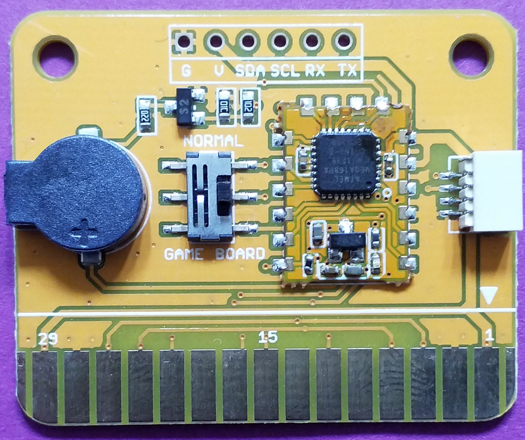
The edge connector (gold fingers) has total of 30 contacts (each side has 15 contacts).
On the front side of the Buzzer card, a white arrow is printed near the edge connector indicates the pin #1. You can find some pin numbers printed on the edge connector itself (1, 15, and 29). You can count the pin numbers starting with 1 and count by twos from right to left would be 1, 3, 7, 9, 11, 15, 17, 19, 21, 23, 27, and 29. Notice that all the counts are odd numbers.
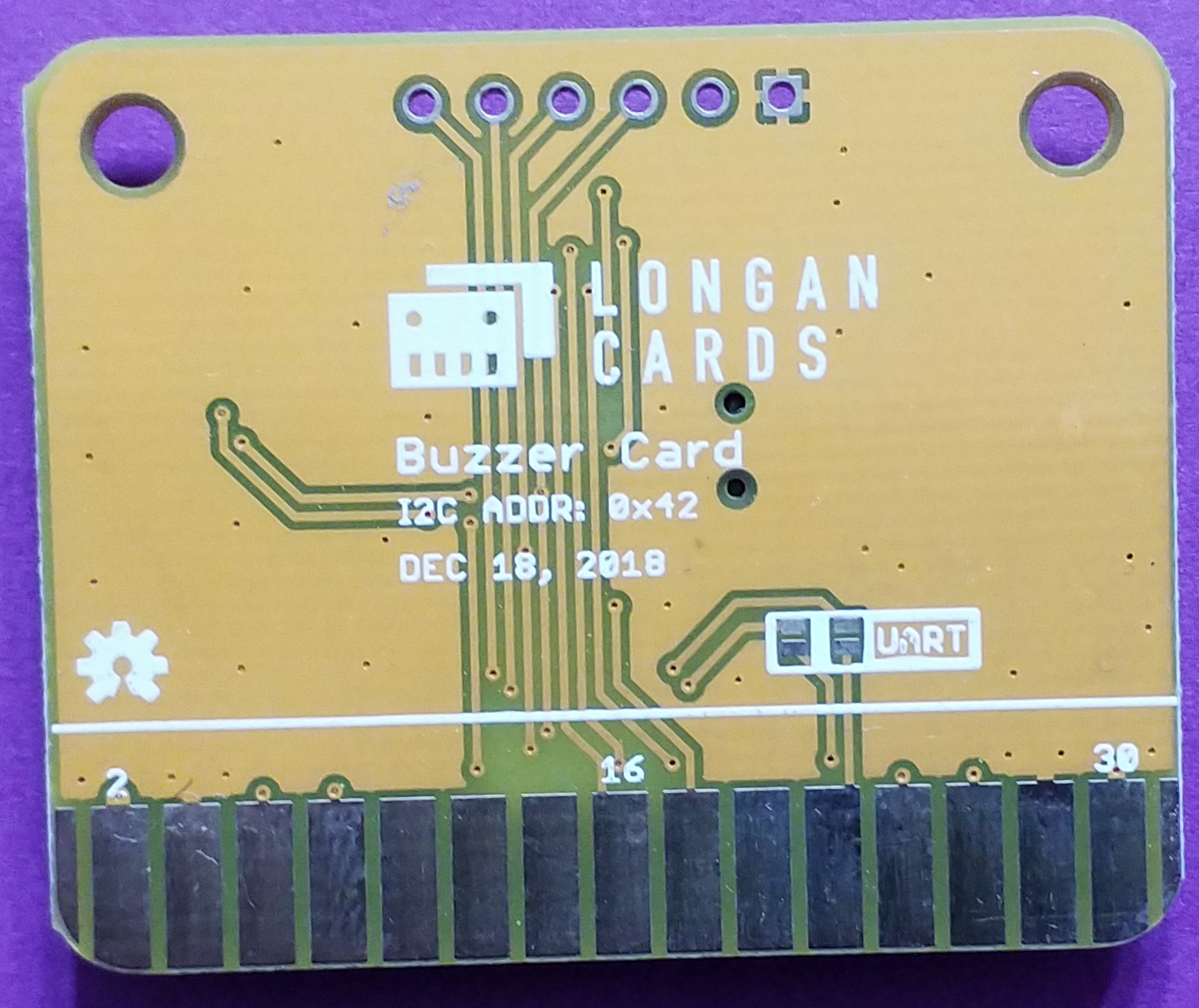
On the back side of the Buzzer card, you also can find some pin numbers printed on the edge connector itself (2, 16, and 30). You can count the pin numbers starting with 2 and count by twos from left to right would be 2, 4, 6, 8, 10, 12, 14, 16, 18, 20, 22, 24, 26, 28 and 30. Notice that all the counts are even numbers.
I2C
Following pins can be used for I2C communication.
SDA: Digital I/O, I2C bus serial bidirectional data line (Front: pin #5, #25 / Back: pin #6, #26) SCL: Digital Input, I2C bus serial clock input (Front: pin #7, #23 / Back: pin #8, #24)
Power
Following pins connect with the common power bus of the board.
VCC: Power supply (Front: pin #1, #29 / Back: pin #2, #30) GND: To be connected to the system ground (Front: pin #3, #27 / Back: pin #4, #28)
Modes
Buzzer card offers two modes.
- BUZ_ CARD mode
- BUZ_MCU mode
BUZ_CARD Mode
The BUZ_CARD mode allows you to control your Buzzer card with the Carduino pin 11 which is equivalent to the Arduino Leonardo digital pin 5. To enable this mode, slide the switch of the Buzzer card to the GAME BOARD position.

Following figure shows the BUZ_CARD mode in detail.
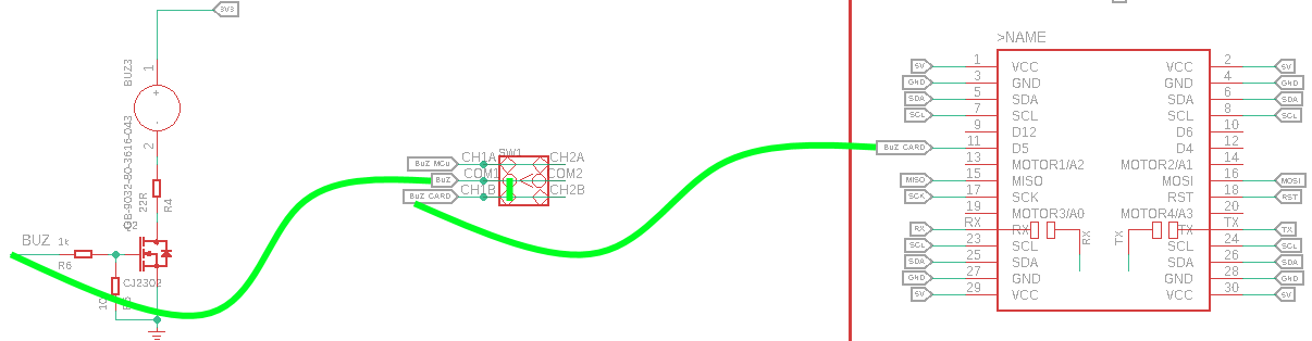
When you slide the switch to the GAME BOARD position, the BUZ and BUZ_CARD will connect together. Also, BUZ_CARD connects with the Carduino pin 11 (Arduino Leonardo digital pin 5, this is also a PWM pin). When you write a sketch, initialize the digital pin 5 as an output.
BUZ_MCU Mode
BUZ_MCU mode connects the buzzer with the ATmega 168P (Arduino Mini digital pin 9) and allows you to program your Carduino to communicate the Buzzer card with I2C communication protocol. Slide the switch of the Buzzer card to the NORMAL position.
Following figure shows the BUZ_MCU mode in detail.
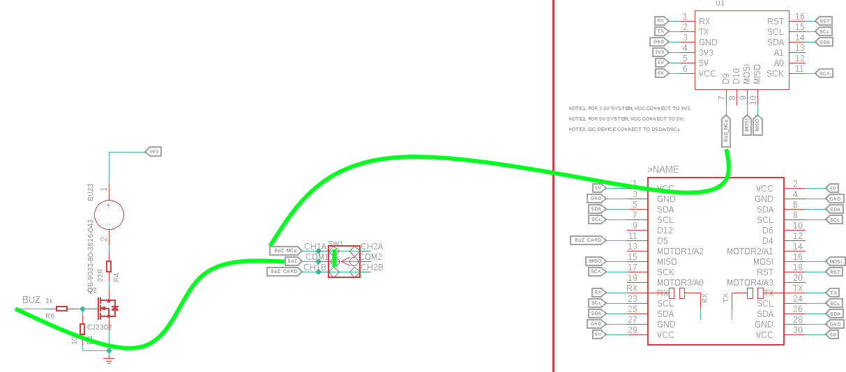
When you slide the switch to the NORMAL position, the BUZ and BUZ_MCU will connect together. Also, BUZ_MCU connects with the ATmega 168P (Arduino Mini digital pin 9, this is also a PWM pin).
The I2C address of the Buzzer card which is 0x42 can be found on the back of the card.
How to Use
The Buzzer card can be plugged into an edge connector slot of one of the following Longan boards.
- Game board
- Car board
- Sensor board
- Extension board
- Pi Hap
When you plugging, the white arrow head printed on the card should be pointing toward the white arrow head printed near the edge connector slot of the board. Once plugged, it can communicate with the Carduino through the I2C bus line and I/O line of the board. It will also connect to the common power bus of the board.
Getting Ready
You can use the extension board to connect any Longan card with the Carduino.
-
First take the Extension board.
-
Next, plug the Buzzer card in to one of the edge connector slot.
-
Then plug the Carduino in to another edge connector slot.
-
Finally, connect the extension board with your computer using a Type-C USB cable (you can use either USB connector on the Carduino or the Extension board).
Playing Sounds
Copy and paste the sketch below into the Arduino editor.
const int buzzer = 5; //buzzer is connected to Carduino pin 11 (Leonardo digital pin 5)

void setup(){
  pinMode(buzzer, OUTPUT); // define pin 5 as an output
}

void loop(){
  tone(buzzer, 1000); // Play 1KHz tone
  delay(1000);        // for 1 second
  noTone(buzzer);     // Stop tone
  delay(1000);        // for 1sec
}
Save the file to your computer's hard drive as buzzer_1.
Connect the Type-C USB cable to the USB connector of the Carduino and connect the other end to your computer.
Slide the switch on the Buzzer card to the GAME BOARD position.
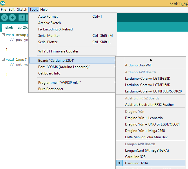
Next, tell the Arduino IDE to use the Carduino. To do this, click Tools > Board > Carduino 32U4 under Longen AVR Boards.
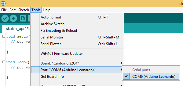
After that, select the proper port in Tools > Port > (the Serial/COM port of your Carduino).
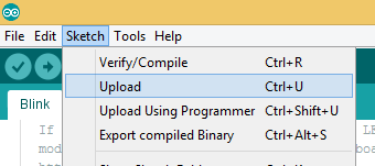
Then upload the program by clicking Sketch > Upload.
It will take some time to compile and upload the sketch into the Carduino. Once uploaded, the buzzer will play a beep-beep sound at 1000 Hz continually.