SERIAL CAN FD MODULE
Introduction
This Grove - CAN BUS Module based on GD32E103 adopts a brand-new design, uses the cost-effective and high-performance GD32E103 microcontroller as the main control and cooperates with a firmware we wrote to complete the function of the serial port to CAN FD.
CAN BUS PRODUCTS LIST OF LONGAN-LABS

We have made a lot of can bus products, you can get more information through the following list, so as to choose a product suitable for you.
| PRODUCT NAME | LINK | PRICE | MCU | CHIP | PROTOCOL |
|---|---|---|---|---|---|
| Serial CAN Bus Module | LINK | $19.9 | ATMEGA168PA | MCP2515 | CAN2.0 |
| I2C CAN Bus Module | LINK | $19.9 | ATMEGA168PA | MCP2515 | CAN2.0 |
| OBD-II Serial CAN Bus Dev Kit | LINK | $20.9 | ATMEGA168PA | MCP2515 | CAN2.0 |
| OBD-II CAN Bus GPS Dev Kit | LINK | $29.9 | ATMEGA32U4 | MCP2515 | CAN2.0 |
| OBD-II CAN Bus Basic Dev Kit | LINK | $24.9 | ATMEGA32U4 | MCP2515 | CAN2.0 |
| CAN-FD Shield | LINK | $19.9 | NO MCU | MCP2517FD | CAN-FD |
| CAN Bus Shield | LINK | $9.9 | NO MCU | MCP2515 | CAN2.0 |
| CANBed | LINK | $24.9 | ATMEGA32U4 | MCP2515 | CAN2.0 |
| CANBed-FD | LINK | $29.9 | ATMEGA32U4 | MCP2517FD | CAN-FD |
| CANBed M4 | LINK | $49.9 | ATSAME51 | - | CAN-FD |
| OBD-II RF Dev Kit | LINK | $19.9 | ATmega168PA | MCP2515 | CAN2.0 |
Note
The above price may not be the latest price, please refer to the price on the product page.
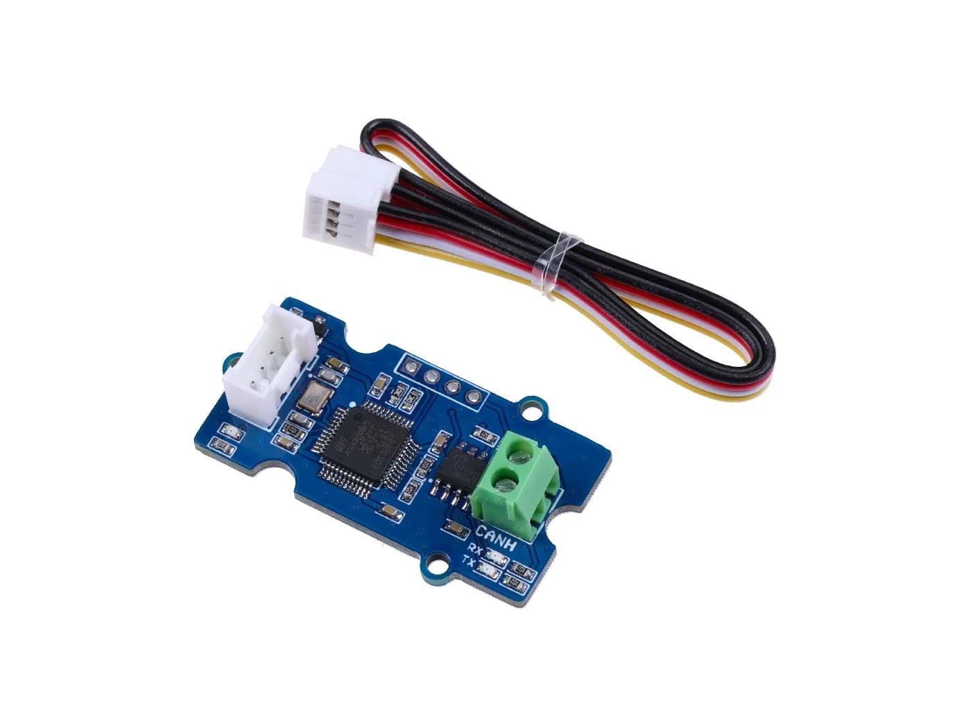
Partlist
Features
- Uart to CAN FD and CAN 2.0
- Work with Arduino/BeagleBone board/Pi or any MCU that integrated with UART.
- AT command
- Up to 115200 Uart baud rate (default 9600)
- Up to 5Mb/s CAN FD baud rate (default 500k)
- TX and RX led indicator
- 4pin HY connector
- 5V working voltage
- Easy-to-use Arduino library
- Small size: 20x40 mm
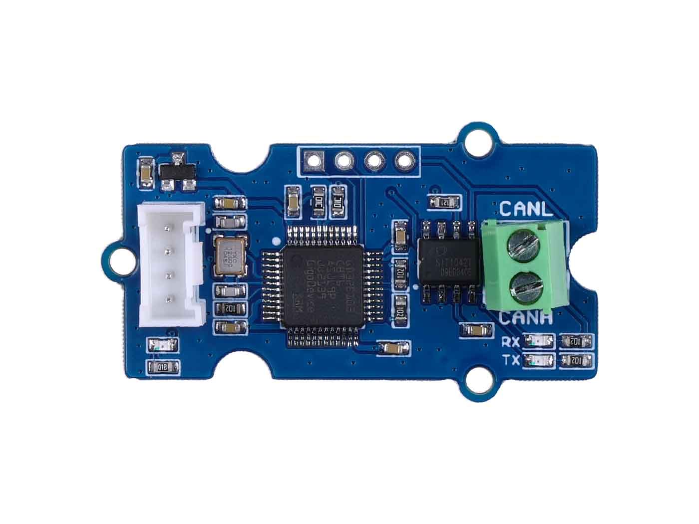
Hardware Overview
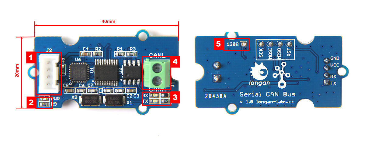
- 4 pin 2.0mm Grove Connector
- Power and status led indicator
- Send and Recv led indicator
- 3.5mm terminal to connect to CAN Bus (CAN_H & CAN_L)
- 120Ω registor.
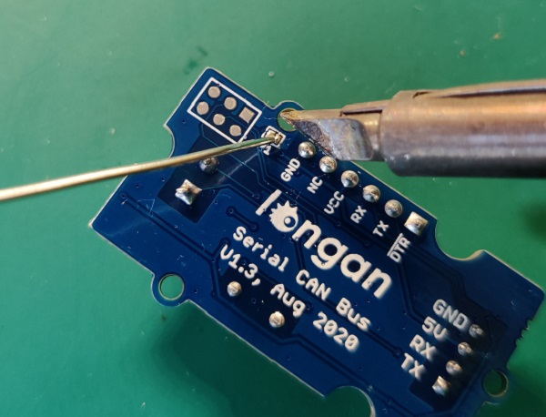
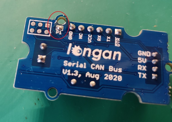
120 Terminal resistor
If you need the 120Ω terminal resistor, you need a soldering iron, as shown below:
AT Command
Send and Recv A CAN FRAME
| Start | Length | Command | ID | EXT | RTR | FDF | Data Length | Data | CRC |
|---|---|---|---|---|---|---|---|---|---|
| 0xAA | / | 0x01 | / | / | / | / | / | / | / |
- Start - 0x0A
- Length - Length for Command to Data
- Command - 0x01
- ID - 4 Byte
- EXT - 1 Byte, 1 for extend frame, 0 for standard frame
- RTR - 1 Byte, 1 for remote frame, 0 for standard frame
- FDF - 1 Byte, 1 for FD frame, 0 for CAN2.0 frame
- Data Length - Length for data
- Data - 1 to 64 byte
- CRC - 2 Byte, CRC
SET THE BAUDARET FOR CAN BUS
| Start | Length | Command | CAN20 Baudrate | CAN-FD Baudrate | CRC |
|---|---|---|---|---|---|
| 0xAA | 0x09 | 0x02 | / | / | CRC |
- Start - 0x0A
- Length - 0x09
- Command - 0x02
- CAN20 Baudrate - 4 Byte, Baudrate for CAN2.0
- CAN-FD Baudrate - 4 Byte, Baudrate for CAN-FD
- CRC - 2 Byte, CRC
SET MASK AND FILTER
| Start | Length | Command | SET | EXT | MASK | FILTER | CRC |
|---|---|---|---|---|---|---|---|
| 0xAA | 0x0B | cmd | 0X01 | EXT | --- | ------ | CRC |
- Start - 0x0A
- Length - 0x0B
- Command - 0x03 for Mask/Filt0, 0x04 for Mask/Filt1, 0x05 for Mask/Filt2, 0x06 for Mask/Filt3
- SET - 0X01
- EXT - 1 for extended frame, 0 for standard frame
- MASK - 4 Byte
- FILTER - 4 Byte
- CRC - 2 Byte, CRC
SET THE UART BAUDRATE
| Start | Length | Command | Uart baudrate | CRC |
|---|---|---|---|---|
| 0xAA | 0x05 | 0x07 | default 9600 | CRC |
- Start - 0x0A
- Length - 0x05
- Command - 0x07
- Uart baudrate - 4 Byte, default 9600kb/s
- CRC - 2 Byte, CRC
About the CRC
The Crc includes the Command and before the CRC data.
The Crc is a simple Crc16. Whenever a frame is parsed by the Master/Slave, it should check that the Crc of the data received matches the frame Crc to establish data integrity.
The Crc field is two bytes, containing a 16-bit binary value. The Crc value is calculated by the transmitting device, which appends the Crc to the message. The receiving device recalculates a Crc during receipt of the message, and compares the calculated value to the actual value it received in the Crc field. If the two values are not equal, an error results.
The Crc is started by first preloading a 16-bit register to all 1's. Then a process begins of applying successive eight-bit bytes of the message to the current contents of the register. Only the eight bits of data in each character are used for generating the Crc. Start and stop bits, and the parity bit, do not apply to the Crc.
During generation of the Crc, each eight-bit character is exclusive ORed with the register contents. Then the result is shifted in the direction of the least significant bit (LSB), with a zero filled into the most significant bit (MSB) position. The LSB is extracted and examined. If the LSB was a 1, the register is then exclusive ORed with a preset, fixed value. If the LSB was a 0, no exclusive OR takes place.
This process is repeated until eight shifts have been performed. After the last (eighth) shift, the next byte is exclusive ORed with the register's current value, and the process repeats for eight more shifts as described above. The final contents of the register, after all the bytes of the message have been applied, is the Crc value.
When the Crc is appended to the message, the low-order byte is appended first, followed by the high-order byte.
Example in C:
// for standard CRC16
// (remainder of division)
// to start a new CRC, set CRC16 = SEED
// then for each byte call CrcCalculate(Byte, CRC16);
// The return of the function will contain the result
// (if you calculate all of the incoming data
// INCLUDING the CRC, the result should be 0x0000
// and if you are sending the CRC be sure to
// send the bytes in the correct order)
// Initialization for CRC16
#define SEED 0xFFFF
// Generating polynomial
#define GP 0xA001
UINT16 Crc16 = SEED;
UINT16 CrcCalculate(UINT8 Byte, UINT16 CRC)
{
    UINT8 Carry;
    int Bit_Index;
    CRC = CRC ^ (Byte & 0xFF);
    for (Bit_Index = 0; Bit_Index < 8; Bit_Index++)
    {
        Carry = CRC & 0x0001;
        CRC = CRC >> 1;
        if (Carry)
        CRC = CRC ^ GP;
    }
    return CRC;
}
Work with Arduino
120Ω Terminal Resistor
As there're only 2 serial can bus device, it need the 120Ω resistor, there's a P1 on the back side, please solder P1 to get the 120Ω resistor, as shown below,
Hardware Connection
There are 4 pins on the board, they are:
| Pin Name | Function | Color |
|---|---|---|
| TX | TX of UART | Yellow |
| RX | RX of UART | White |
| 5V | VCC, connect to 5V, 3.3V is not work for this module | Red |
| GND | Ground | Black |
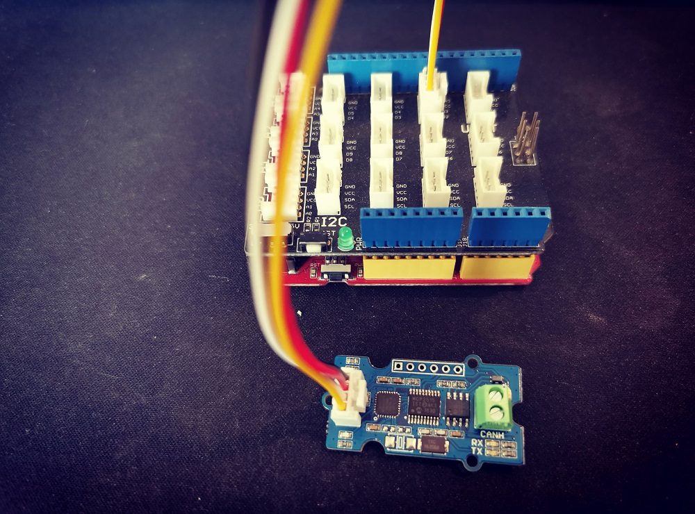
If you got a Base Shield from Seeedstudio, the connection is easy, like below,
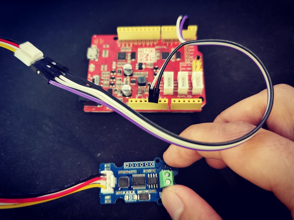
If there's no Base Shield for you, you need some dupont cable, and connect TX/RX to the IO of your Arduino, here we connect TX/RX to D2/D3:
Note
Not all pins on the Mega and Mega 2560 support change interrupts, so only the following can be used for RX: 10, 11, 12, 13, 14, 15, 50, 51, 52, 53, A8 (62), A9 (63), A10 (64), A11 (65), A12 (66), A13 (67), A14 (68), A15 (69).
Software
We provide an library for Aruino Software Serial.
Please download it at Github
There're many examples for the library, which is consist of,
- can_speed_fd - Send the can bus baudrate for CAN-FD
- can_speed_20 - Send the can bus baudrate for CAN2.0
- can_send - Send a CAN frame to the bus
- read_can - Read a CAN frame from the bus
- set_mask_filt - Set the mask and filt for recving
- set_baudrate - Set the Uart baudrate, default 9600kb/s
Test the board
Here we make an example to show you how the board work with CAN Bus.
The connection like below, here we use Seeeduino + Serial CAN bus module as the receiver, and a USB2Uart module + Serial CAN bus module as sender.
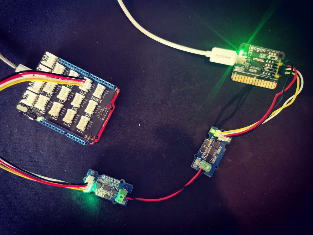
If you send the command of sending frame to the USB2Uart module, open the Arduino serial monitor, you will get data from CAN Bus.
FAQ
The RX and TX leds light up instead of blinking
- Please check the baudrate of CAN Bus
- If the serial can bus module is in the end, the 120Ω terminal resistor is needed, please soder P1 on the back side of PCBA
Don't work with Arduino Mega
Not all pins on the Mega and Mega 2560 support change interrupts, so only the following can be used for RX: 10, 11, 12, 13, 14, 15, 50, 51, 52, 53, A8 (62), A9 (63), A10 (64), A11 (65), A12 (66), A13 (67), A14 (68), A15 (69).
How to find the tech support
Please contact support@longan-labs.cc for technical support. Our technical support engineer will usually reply you within 24 hours on working days. In order to get faster support, we hope that when you send us an email, you need to include at least the following content,
- When and how to buy the product
- Product version information
- Take a high-definition picture of the product you use, including the connection
- Describe in detail the problem you encountered and what kind of help you would like to get