Light Sensor Card
Introduction
The Longan Light Sensor Card features TEMT6000 ambient light sensor. It is sensitive to the visible spectrum. With Longan Light Sensor Card, you can bring the ability to detect light level to any project.
The light sensor on the Light Sensor Card will detect the intensity of light of its surroundings. It outputs values ranging from 0 - 1023 where 0 indicates dark and 1023 indicates bright light. If you want to get the visible light intensity in lux (lx), check out our other version here.
NOTE: The Light sensor card supports two wire I2C bus interface.
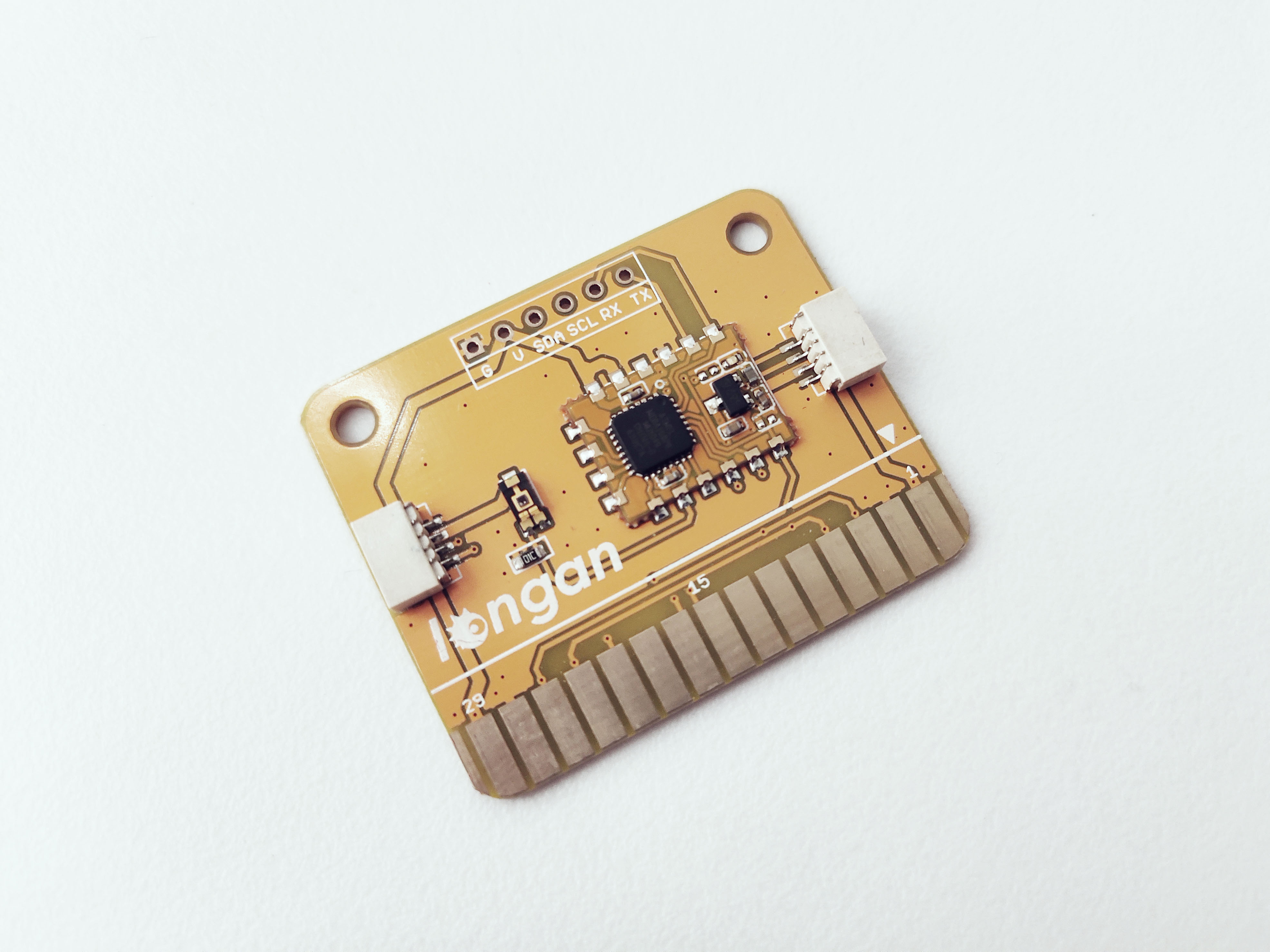
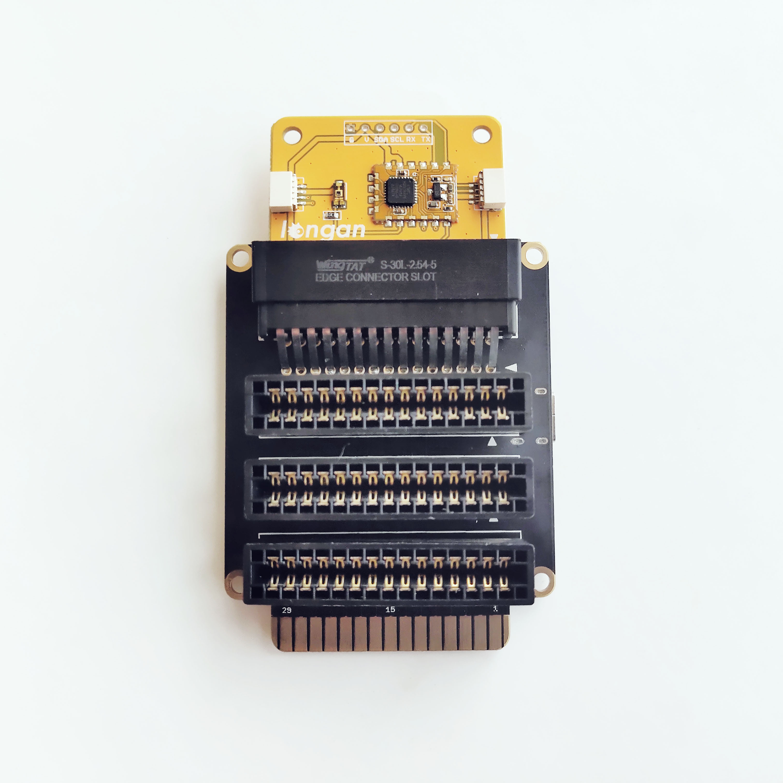
The front of the Light Sensor Card has following components.
- TEMT6000 silicon NPN epitaxial planar phototransistor (http://pdf1.alldatasheet.com/datasheet-pdf/view/117488/VISHAY/TEMT6000.html)
- 30 gold fingers (30 pin edge connector) - allows you to plug the card into any edge connector slot of a Longan board.
- ATmega 168PA microprocessor - runs card firmware.
- LED indicator – flashes when Carduino read/write data from/to the card through I2C.
- Two 4 pin SH1.0 connectors - allows you to connect MCUs or cards which support I2C communication protocol with dupont cables.
Specifications
- Voltage: 5V
- Adapted to human eye responsivity
- Wide angle of half sensitivity ϕ = ± 60°
- Supports two wire I2C bus interface
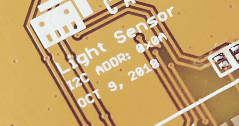
I2C Address
The default I2C address is printed on the back side of the card which is 0x08. However, you can change it to a different address with the card firmware (Read our wiki for how to change the default I2C address of a card.).
Pins
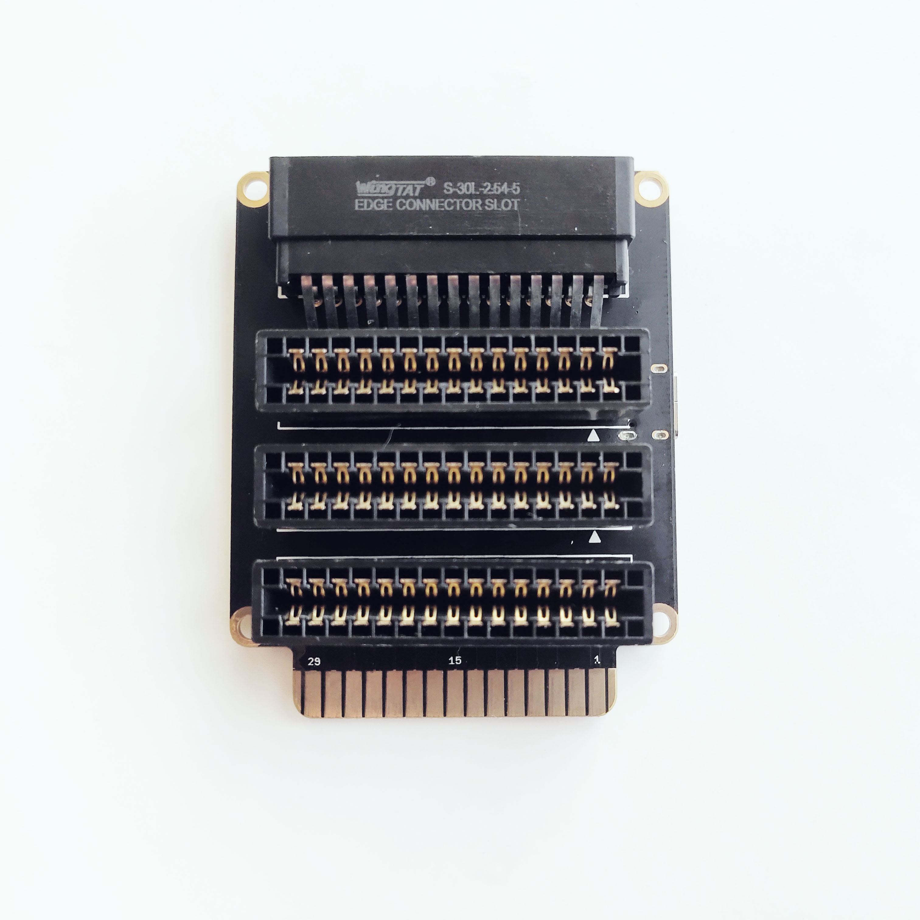
The edge connector (gold fingers) has total of 30 contacts (each side has 15 contacts).
On the front side of the Light sensor card, a white arrow is printed near the edge connector indicates the pin #1. You can find some pin numbers printed on the edge connector itself (1, 15, and 29). You can count the pin numbers starting with 1 and count by twos from right to left would be 1, 3, 7, 9, 11, 15, 17, 19, 21, 23, 27, and 29. Notice that all the counts are odd numbers.
On the back side of the Light sensor card, you also can find some pin numbers printed on the edge connector itself (2, 16, and 30). You can count the pin numbers starting with 2 and count by twos from left to right would be 2, 4, 6, 8, 10, 12, 14, 16, 18, 20, 22, 24, 26, 28 and 30. Notice that all the counts are even numbers.
Among the 30 pins, following pins can be used for I2C communication.
- SDA: Digital I/O, I2C bus serial bidirectional data line (Front: pin #5, #25 / Back: pin #6, #26)
- SCL: Digital Input, I2C bus serial clock input (Front: pin #7, #23 / Back: pin #8, #24)
Also, following pins connect with the common power bus of the board.
- VCC: Power supply (Front: pin #1, #29 / Back: pin #2, #30)
- GND: To be connected to the system ground (Front: pin #3, #27 / Back: pin #4, #28)
How to Use
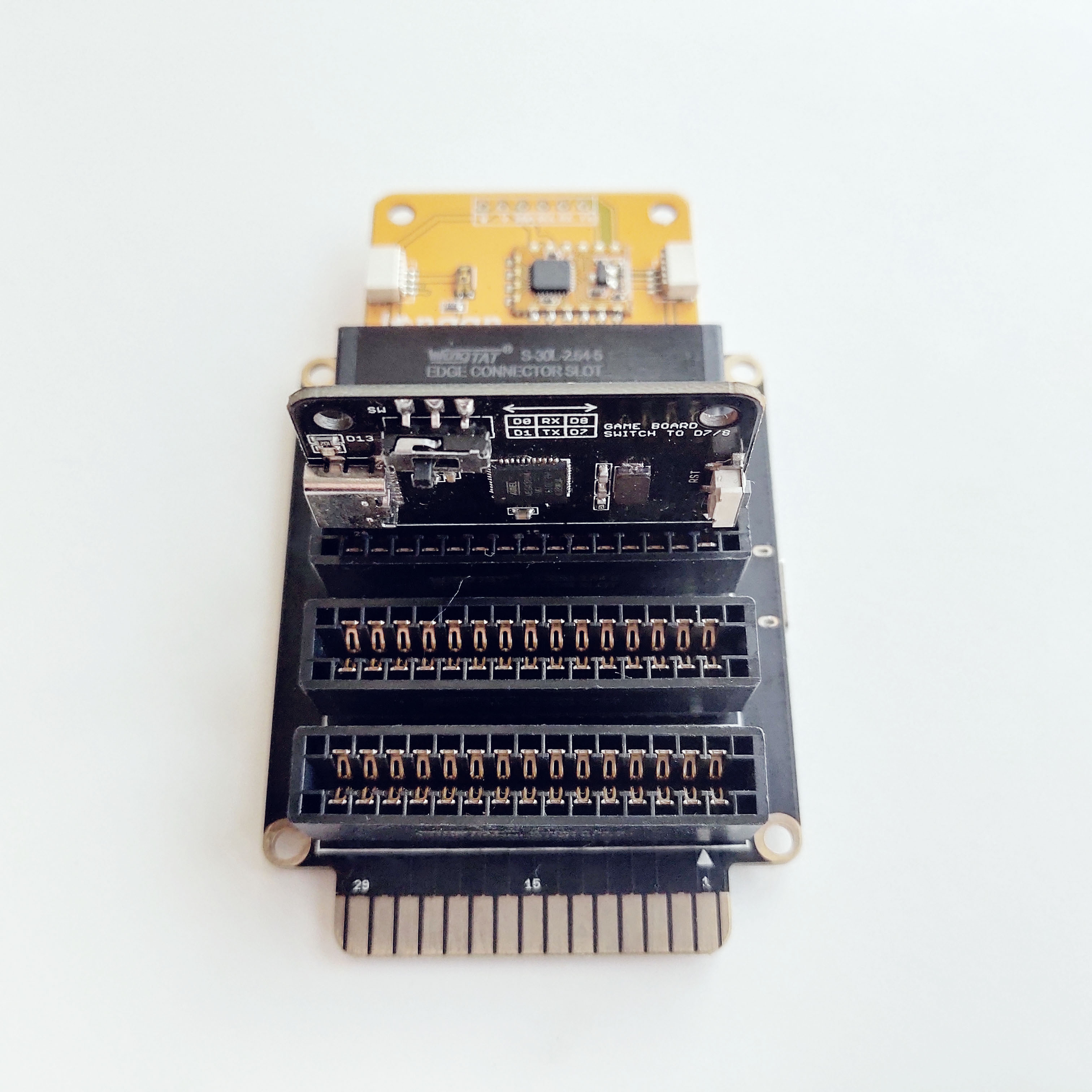
The Light sensor card can be plugged into an edge connector slot of one of the following Longan boards.
- Game board
- Car board
- Sensor board
- Extension board
- PI Hap
When you plug, the white arrow head printed on the card should be pointing toward the white arrow head printed near the edge connector slot of the board. Once plugged, it can communicate with the Carduino through the I2C bus line of the board. It will also connect to the common power bus of the board.
Use with Extension Board
You can use the extension board to connect any Longan card with the Carduino.
-
Take the Extension board.
-
Plug the Light sensor card into one of the edge connector slot.
-
Plug the Carduino into another edge connector slot.
-
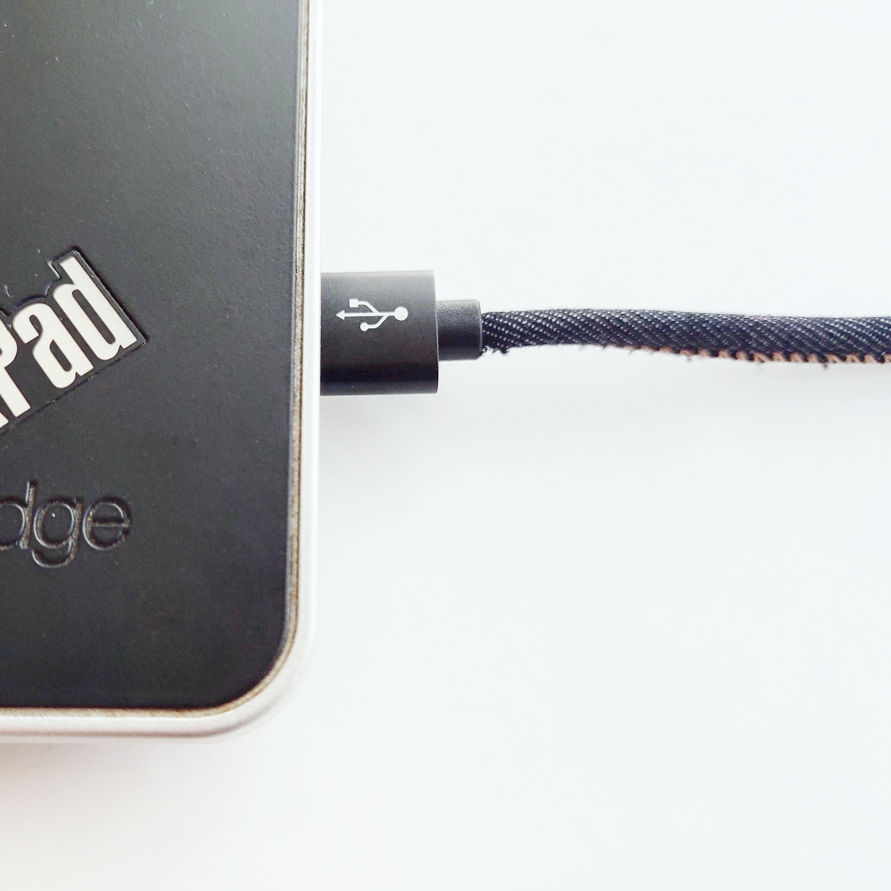
Connect the extension board with your computer using a Type-C USB cable (you can use either USB connector on the Carduino or the Extension board).
Reading Visible Light Intensity
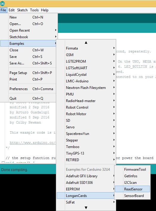
The sample code can be loaded to your Arduino IDE by clicking on File > Examples > LonganCards > ReadSensor.
If you have trouble loading the sketch from the examples, you can copy and paste the code below into the Arduino editor.
#include <Wire.h>
#include "CardsDfs.h"
#include "LonganCards.h"

CARD_INFO card;

int addr = 0;
int cntSensor = 0;

float sensorValue[10];

float str2num(unsigned char *str)
{
    float num = 0;
    memcpy((unsigned char *)(&num), str, 4);
    return num;
}

void setup() {
    // put your setup code here, to run once:
    Serial.begin(115200);
    Wire.begin();

    while(!Serial.available());

    addr = card.scan();
    if(0 == addr)
    {
        Serial.println("NO DEVICE!");
        while(1);
    }

    card.getInfo();
    card.disp();

    cntSensor = card.senCnt;
}

void loop()
{
    for(int i=0; i<cntSensor; i++)
    {
        sensorValue[i] = getValue(i);
        Serial.print(sensorValue[i], 2);
        Serial.print('\t');
    }

    Serial.println();
    delay(100);
}

float getValue(int s)
{
    unsigned char dta[10];
    unsigned long len = 0;

    Wire.beginTransmission(addr);
    Wire.write(REG_VALUE_START+s);      // ADDR_DATA_START = 0x30
    Wire.endTransmission();

    delay(1);
    Wire.requestFrom(addr, 6);

    delay(1);

    while(Wire.available())
    {
        dta[len++] = Wire.read();
    }

    return str2num(&dta[1]);
}

// END FILE
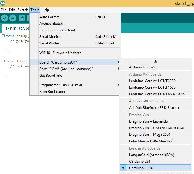
Next, tell the Arduino IDE to use the Carduino. To do this, click Tools > Board > Carduino 32U4 under Longen AVR Boards.
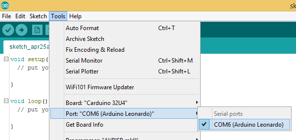
Then select the proper port in Tools > Port > (the Serial/COM port of your Carduino).
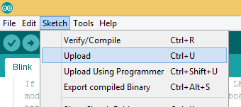
Next, upload the program by clicking Sketch > Upload.
It will take some time to compile and upload the sketch in to the Carduino.
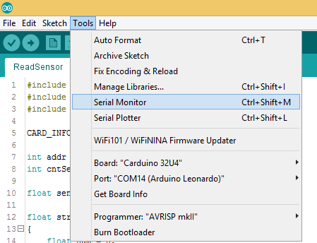
Once uploaded, open the Serial Monitor by clicking Tools > Serial Monitor.
In the Serial Monitor, type any number or character and click Send button.
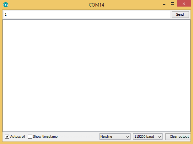
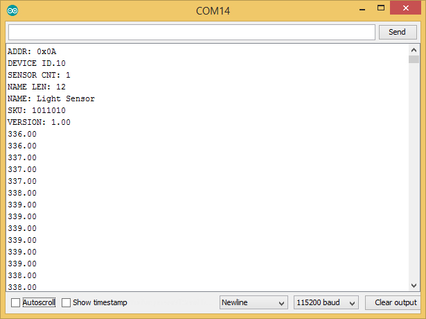
First, it will print the device information of your Light sensor card such as I2C address, device id, number of sensors, name length, name, SKU, and version to Serial Monitor. Then the real-time light sensor levels will print to Serial Monitor repeatedly. The values will fall between 0 - 1023.
The blue LED on the ATmega 168P module will blink quickly and continually during the illuminance reading through I2C.
Labs
Lab 01
To perform this lab you will need:
- Light Sensor Card
- Carduino 32U4
- OLED Display Card
- Extension Board
- USB to Type-C Cable (https://www.longan-labs.cc/2140001.html)
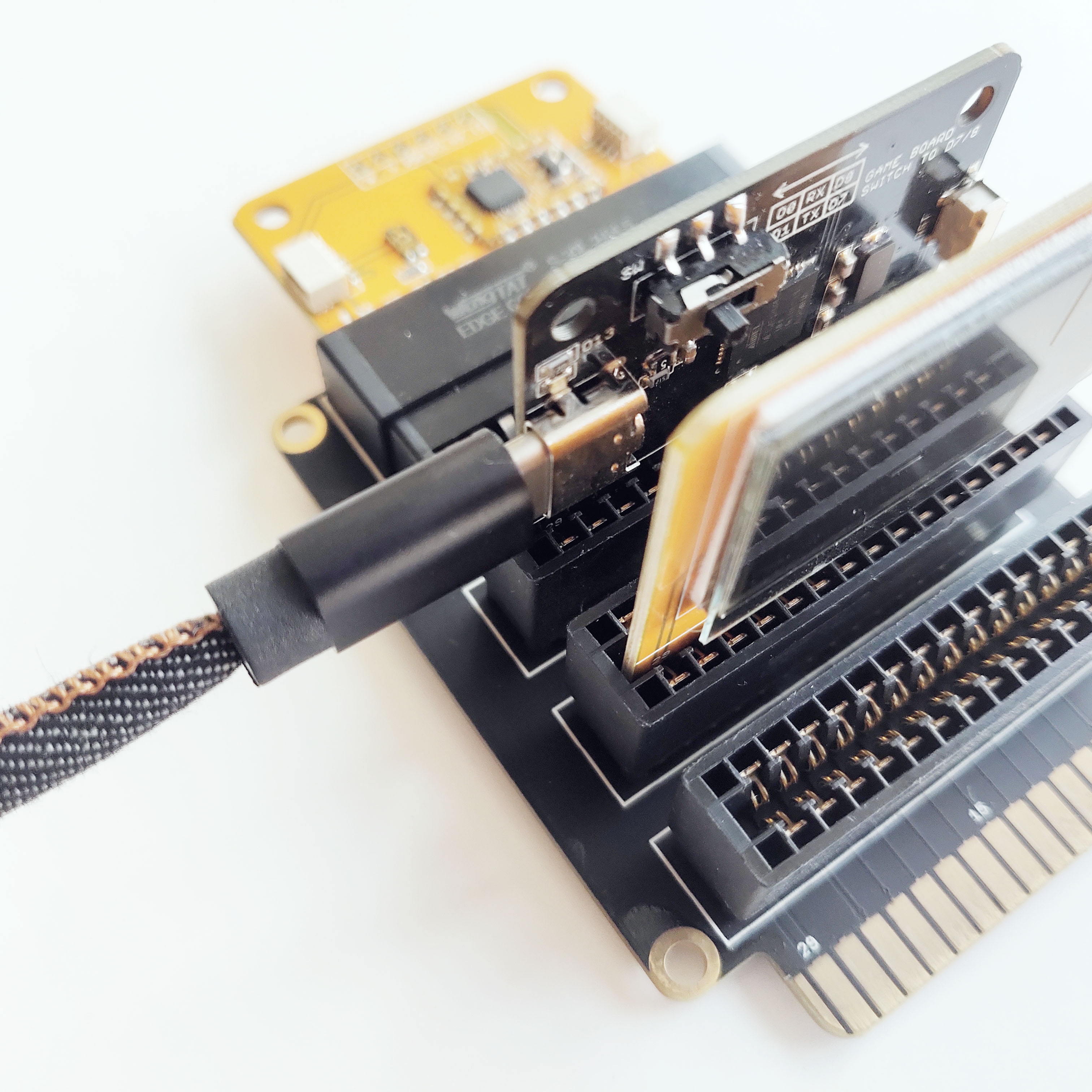
Assembly
Plug your cards into the slots of the Extension Board. The Extension Board will work no matter which cards are attached where. Then connect the Cardiono to the computer using USB to Type-C cable.
NOTE: The Light Sensor Card outputs values ranging from 0 - 1023 where 0 indicates dark and 1023 indicates bright light.
Applications
Can you think of an application where a light sensor would be useful?
Light sensors can be used for automatic lighting applications, such as your mobile phone that automatically adjust the brightness of the screen according to the amount of light that reaches it's light sensor and your car automatically turn on lights at dark depending on the amount of light that reaches to it's rain-light sensor. Images coming soon.
Code
Copy and paste the code from below into your Arduino IDE. Verify and upload the program onto your Carduino 32U4.
You will see the real-time light sensor levels (0 - 1023) will print to screen repeatedly.
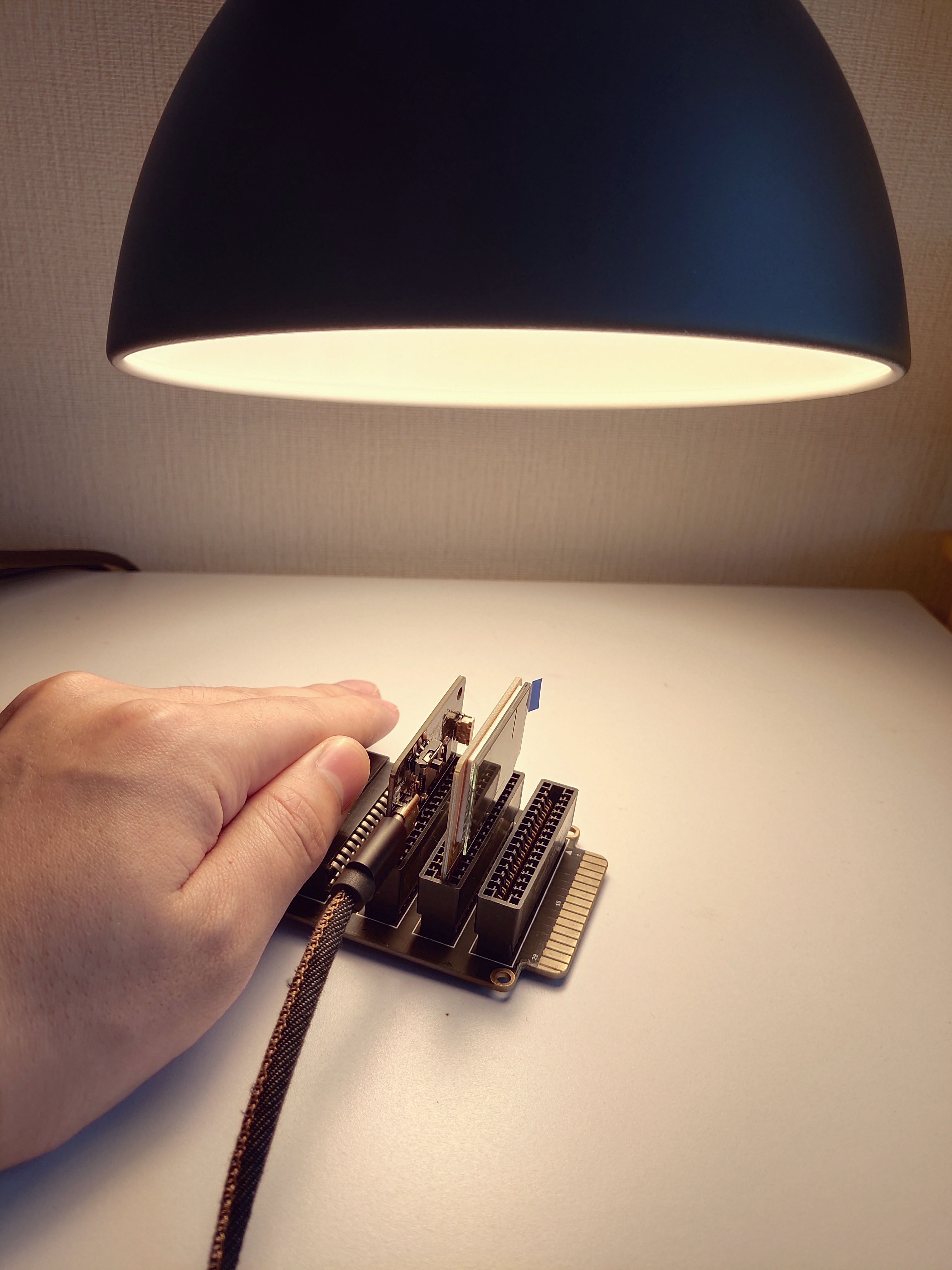
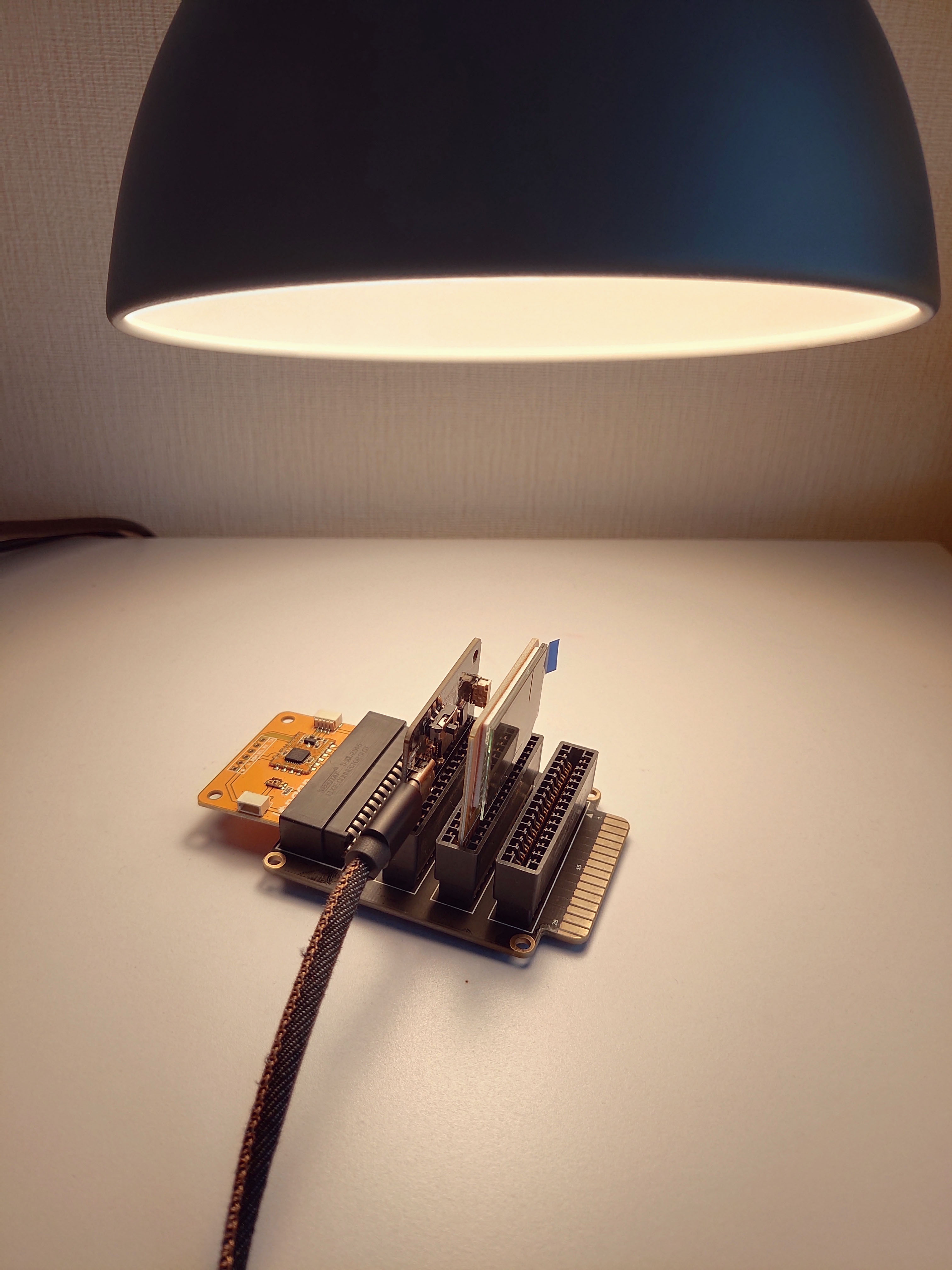
Place the light sensor unit under a lamp.
Now gently cover the Light Sensor Card with your hand. This will reduce the amount of light that reaches the sensor to nearly zero.