CAN-FD SHIELD
CAN-BUS is a common industrial bus because of its long travel distance, medium communication speed and high reliability. It is commonly found on modern machine tools, such as an automotive diagnostic bus.
This CAN-FD Shield adopts MCP2517 CAN Bus controller with SPI interface and MCP2542 CAN transceiver to give your Arduino CAN-BUS(CAN-FD) capability. With an OBD-II converter cable added on and the OBD-II library imported, you are ready to build an onboard diagnostic device or data logger.
Note
For transportation considerations, the plug-in components of the kit are not soldered by default. After you receive the kit, you need to do some soldering work. If necessary, you can also contact info@longan-labs.cc after purchasing the board, then we can send it to you after the board is soldered well.
CAN BUS PRODUCTS LIST OF LONGAN LABS

We have made a lot of can bus products, you can get more information through the following list, so as to choose a product suitable for you.
| PRODUCT NAME | LINK | PRICE | MCU | CHIP | PROTOCOL |
|---|---|---|---|---|---|
| Serial CAN Bus Module | LINK | $19.9 | ATMEGA168PA | MCP2515 | CAN2.0 |
| I2C CAN Bus Module | LINK | $19.9 | ATMEGA168PA | MCP2515 | CAN2.0 |
| OBD-II Serial CAN Bus Dev Kit | LINK | $20.9 | ATMEGA168PA | MCP2515 | CAN2.0 |
| OBD-II CAN Bus GPS Dev Kit | LINK | $29.9 | ATMEGA32U4 | MCP2515 | CAN2.0 |
| OBD-II CAN Bus Basic Dev Kit | LINK | $24.9 | ATMEGA32U4 | MCP2515 | CAN2.0 |
| CAN-FD Shield | LINK | $19.9 | NO MCU | MCP2517FD | CAN-FD |
| CAN Bus Shield | LINK | $9.9 | NO MCU | MCP2515 | CAN2.0 |
| CANBed | LINK | $24.9 | ATMEGA32U4 | MCP2515 | CAN2.0 |
| CANBed-FD | LINK | $29.9 | ATMEGA32U4 | MCP2517FD | CAN-FD |
| CANBed M4 | LINK | $49.9 | ATSAME51 | - | CAN-FD |
| OBD-II RF Dev Kit | LINK | $19.9 | ATmega168PA | MCP2515 | CAN2.0 |
Note
The above price may not be the latest price, please refer to the price on the product page.
Features
- Work at CAN-FD and CAN 2.0
- Industrial standard 9 pin sub-D connector
- OBD-II and CAN standard pinout selectable.
- Changeable chip select pin
- Changeable CS pin for TF card slot
- Changeable INT pin
- Arduino Uno pin headers
- 2 Grove connectors (I2C and A0/A1)
- SPI Interface up to 10 MHz
Note
CAN-FD Shield Work well with Arduino UNO (ATmega328), Arduino Mega (ATmega1280/2560) as well as Arduino Leonardo (ATmega32U4).
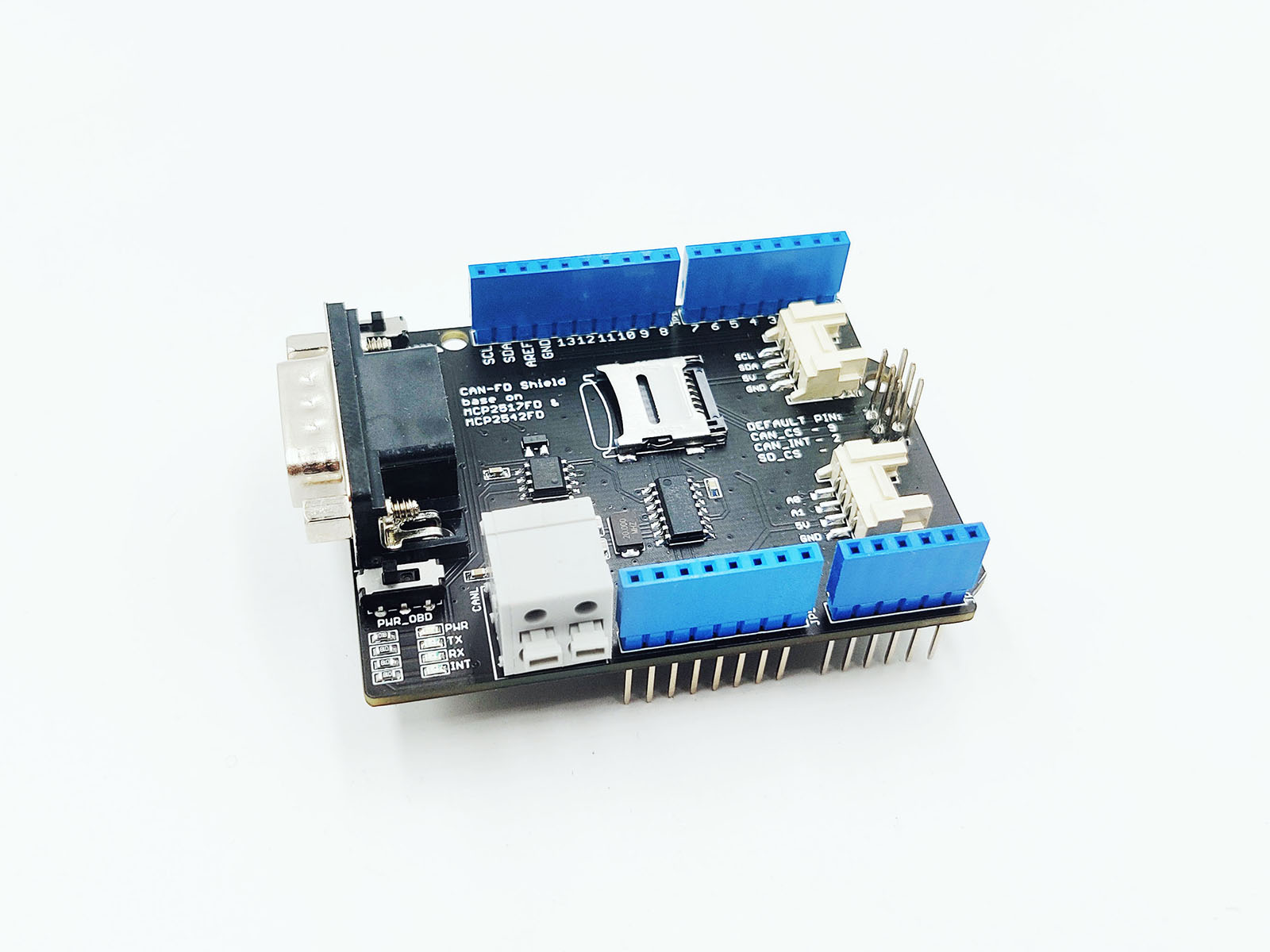
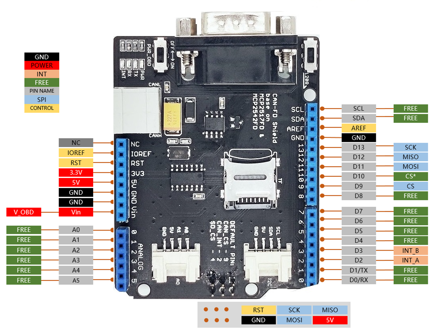
Hardware Overview
- DB9 Interface - to connect to OBDII Interface via a DBG-OBD Cable.
- V_OBD - It gets power from OBDII Interface (from DB9)
- Led Indicator:
- PWR: power
- TX: blink when the data is sending
- RX: blink when there's data receiving
- INT: data interrupt
- Terminal - CAN_H and CAN_L
- Arduino UNO R3 pin out
- A0/A1 Grove connector
- I2C Grove connector
- ICSP pins
- IC - MCP2542FD, a high-speed CAN-FD transceiver (datasheet)
- IC - MCP2517FD, stand-alone CAN controller with SPI interface (datasheet)
- SD card slot
- 120Ω terminal resistor switch
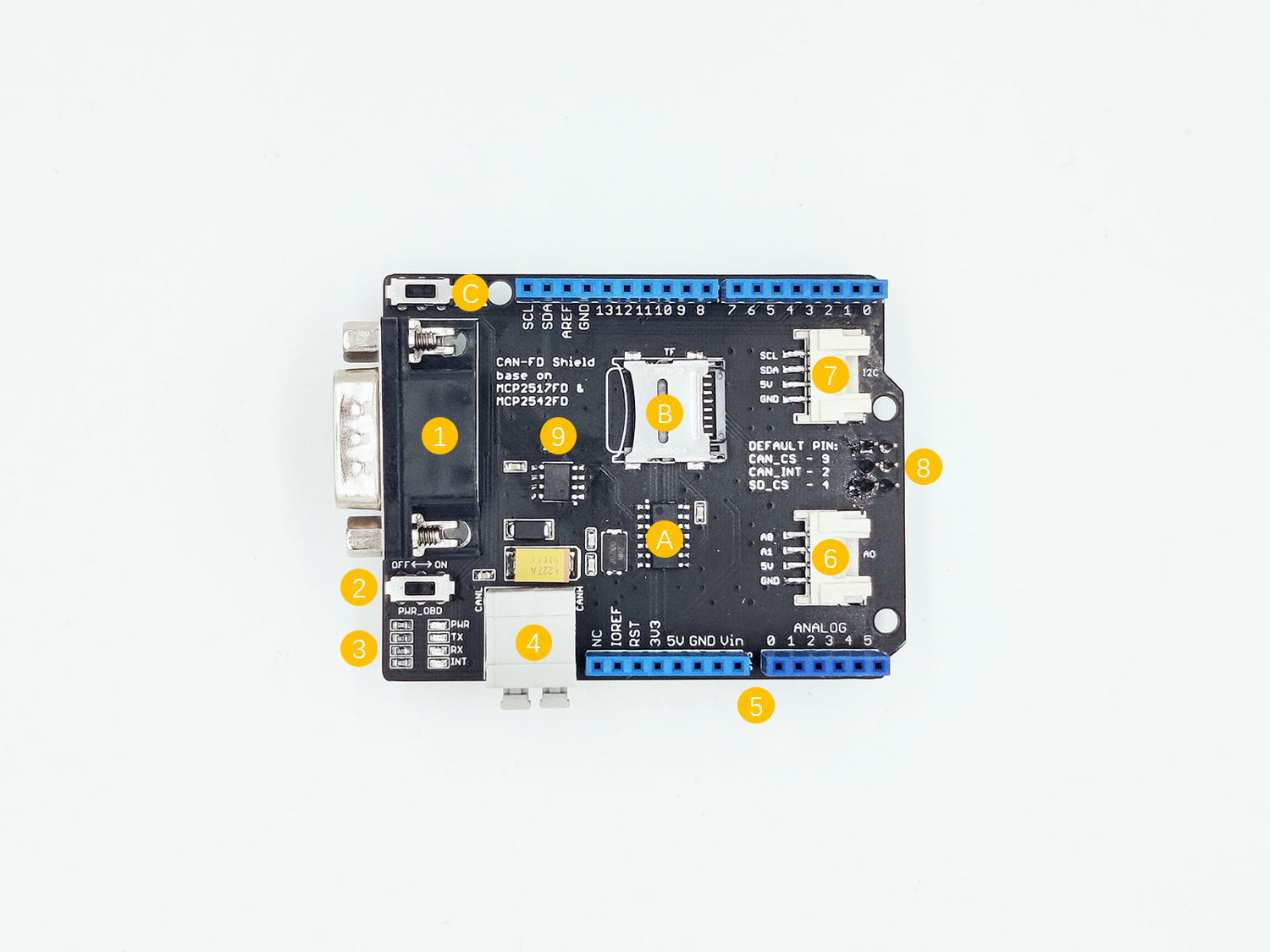
DB9 connector
The DB9 interface of CAN Bus has two different protocols, OBD and CAN Open. Their definition is as follows,
| pin# | OBD(default) | CAN OPEN |
|---|---|---|
| 1 | GND | N.C |
| 2 | GND | CAN_L |
| 3 | CANH | GND |
| 4 | N.C | N.C |
| 5 | CANL | GND |
| 6 | N.C | N.C |
| 7 | N.C | CAN_H |
| 8 | N.C | N.C |
| 9 | CAN_V+ | CAN_V+ |
If you want to use the OBD protocol, you don't need to make any changes to the hardware.
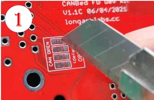
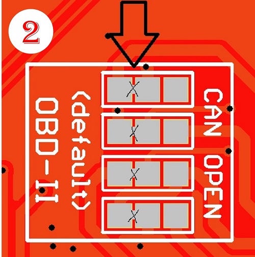
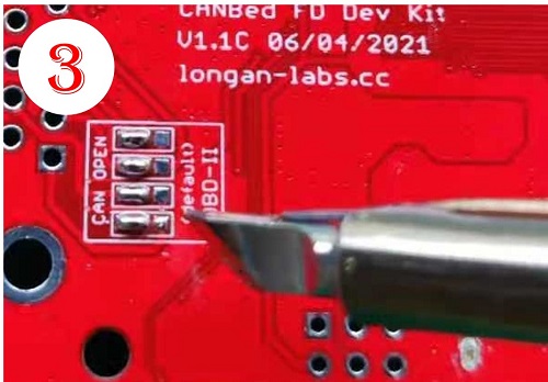
If you need to use the CAN Open protocol, first we look at the back side of the PCB board, you can see the Pads below,
Note
The picture shows another board, but it doesn't matter, the operation method is the same.
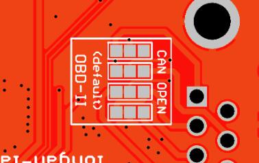
These pads are connected to the OBD side by default. We have to prepare a knife to disconnect the OBD side, and then use an electric soldering iron to solder the CAN Open side of the pads.
Pin map
Note
- The FREE pin is available for the other usages.
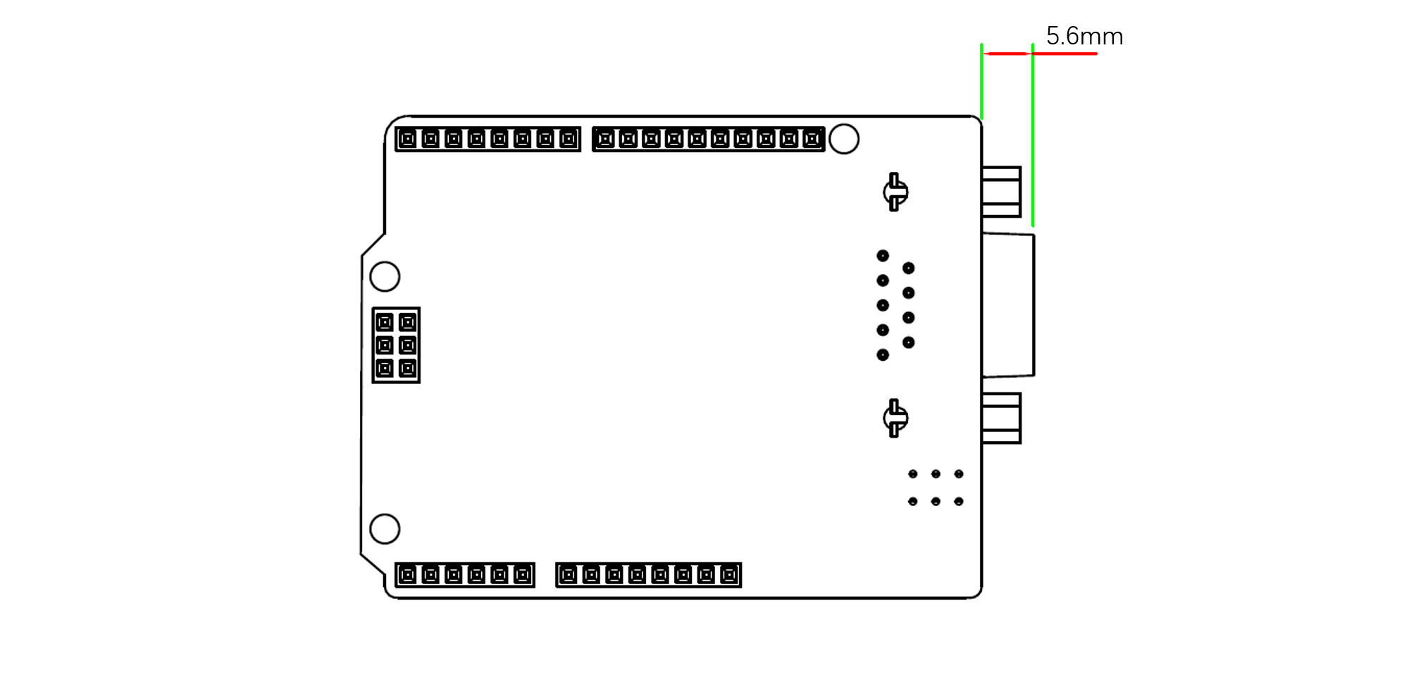
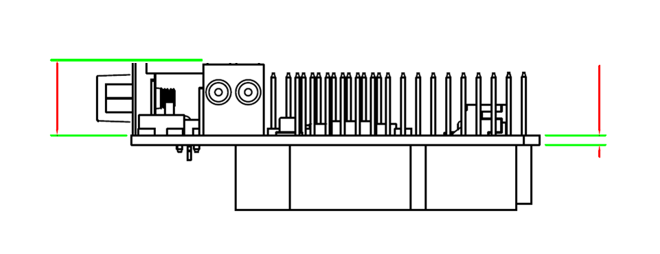
Dimensions

Getting Started
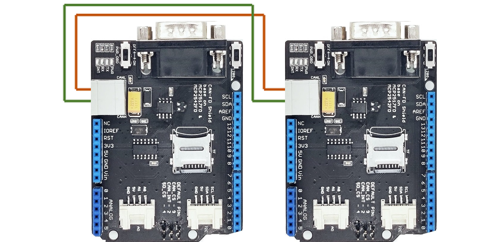
Here's a simple example to show you how CAN-BUS Shield works. In this example we need 2 pieces of CAN-BUS Shields as well as Longan Core 01.
Note
This example is built under Arduino IDE version 1.8.10.
STEP1: What do we need
| Name | Function | Qty | Link |
|---|---|---|---|
| CAN-FD Shield | CAN Bus communication | 2 | GET ONE NOW |
| Longan Core 01 | Controller | 2 | GET ONE NOW |
STEP2: Hardware Connection
Insert each CAN-BUS Shield into Longan Core 01, and connect the 2 CAN-BUS Shield together via 2 jumper wires. Shown as below images.
Note
CAN_H to CAN_H, CAN_L to CAN_L
STEP3: Software
Please follow how to install an arduino library procedures to install CAN BUS shield library.
Click CAN-FD Library for Arduino to download the library.
Install the library to your Arduino IDE when it is downloaded.
One of the node (a node means Longan Core 01 + CAN_BUS Shield) acts as master, the other acts as slaver. The master will send data to slaver constantly.
Note
Each node can act as master before the code being uploaded.
Open the CANFD_Send example (File > Examples > Longan_CANFD > CANFD_Send) and upload to the master.
Open the CANFD_RECV_INT example (File > Examples > Longan_CANFD > CANFD_RECV_INT) and upload to the slaver.
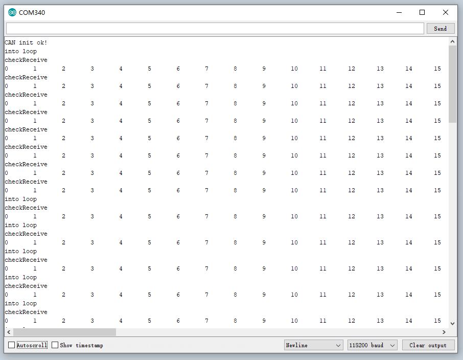
STEP4: View Result
Open the Serial Monitor of Arduino IDE(slaver), you will get the data sent from the master.
Get data from a Vehicle
We can use CANFD Shield to get data from a vehicle, we take the vehicle speed for an example here.
You can use our products to read data from cars. Here we provide a simple example by which you can read the speed and revs from a car. This is the OBD-based PIDs protocol. Regarding the deeper technology of OBD, we can't provide support at present. You may need to have some understanding of the car's protocol. After all, we are more of a hardware supplier.
The interface of OBD is as follows,
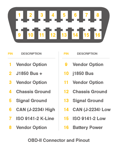
There're 4 pins we need to connect.
| OBD Pin | CANFD Shield |
|---|---|
| 5. Signal Ground | GND |
| 6. CAN(J-2234) High | CANH |
| 14. CAN(J-2234) Low | CANL |
| 16. Battery Power | VIN |
You can also use our OBD-II to DB9 Cable, which is very convenient to connect to OBD.
Upload the following code to the development board, then open the serial monitor, you get the speed from the car now.
#include <SPI.h>
#include "mcp2518fd_can.h"

// pin for CAN-FD Shield
const int SPI_CS_PIN = 9;
const int CAN_INT_PIN = 2;

// pin for CANBed FD
//const int SPI_CS_PIN = 17;
//const int CAN_INT_PIN = 7;

mcp2518fd CAN(SPI_CS_PIN); // Set CS pin

#define PID_ENGIN_PRM       0x0C
#define PID_VEHICLE_SPEED   0x0D
#define PID_COOLANT_TEMP    0x05

#define CAN_ID_PID          0x7DF

unsigned char PID_INPUT;
unsigned char getPid    = 0;

void set_mask_filt() {
    CAN.init_Filt_Mask(0, 0, 0x7E8, 0x7FC);
}

void sendPid(unsigned char __pid) {
    unsigned char tmp[8] = {0x02, 0x01, __pid, 0, 0, 0, 0, 0};
    CAN.sendMsgBuf(CAN_ID_PID, 0, 8, tmp);
}

bool getSpeed(int *s)
{
    sendPid(PID_VEHICLE_SPEED);
    unsigned long __timeout = millis();

    while(millis()-__timeout < 1000)      // 1s time out
    {
        unsigned char len = 0;
        unsigned char buf[8];

        if (CAN_MSGAVAIL == CAN.checkReceive()) {                // check if get data
            CAN.readMsgBuf(&len, buf);    // read data,  len: data length, buf: data buf

            if(buf[1] == 0x41)
            {
                *s = buf[3];
                return 1;
            }
        }
    }

    return 0;
}

void setup() {
    Serial.begin(115200);
    while(!Serial);

    while (CAN_OK != CAN.begin(CANFD_500KBPS)) {             // init can bus : baudrate = 500k
        Serial.println("CAN init fail, retry...");
        delay(100);
    }
    Serial.println("CAN init ok!");
    set_mask_filt();
}

void loop() {

    int __speed = 0;
    int ret = getSpeed(&__speed);
    if(ret)
    {
        Serial.print("Vehicle Speed: ");
        Serial.print(__speed);
        Serial.println(" kmh");
    }
    delay(500);
}

// END FILE
FAQ
How to find the tech support
Please contact support@longan-labs.cc for technical support. Our technical support engineer will usually reply you within 24 hours on working days. In order to get faster support, we hope that when you send us an email, you need to include at least the following content,
- When and how to buy the product
- Product version information
- Take a high-definition picture of the product you use, including the connection
- Describe in detail the problem you encountered and what kind of help you would like to get