SERIAL CAN BUS MODULE
Introduction
The Serial CAN BUS provide your Arduino or others MCU with the capability to communication to CAN Bus, such as hacking your vehicle. CAN Bus is a common industrial bus because of its long travel distance, medium communication speed and high reliability.
This Serial CAN Bus module is based on MCP2551 and MCP2515, which can provide speed up to 1Mb/s.
Note
Because the Arduino library provided by this module uses a soft serial port, it is only suitable for AVR series Arduino, such as Arduino UNO, Arduino Mega, Arduino Leonardo, etc. If you use other non-AVR series Arduino, you may need to modify the library to use it.
Note
The default masks and filters is for standard can frame, if you need to receive a ext can frame, please set the mask and filt first.
Version Track
| Version | VCC | IO Level | MCU | Others Change |
|---|---|---|---|---|
| V1.0 | 5V | 5V | Atmega328P | NO |
| V1.1 | 5V | 5V/3.3V | Atmega328P | Add a pads for the 3.3V IO |
| V1.2 | 5V | 5V/3.3V | Atmega168PA | Change the MCU to Atmega168PA |
| V1.3 | 5V/3.3V | 5V/3.3V | Atmega168PA | Support 3.3V VCC |
CAN BUS PRODUCTS LIST OF LONGAN-LABS

We have made a lot of can bus products, you can get more information through the following list, so as to choose a product suitable for you.
| PRODUCT NAME | LINK | PRICE | MCU | CHIP | PROTOCOL |
|---|---|---|---|---|---|
| Serial CAN Bus Module | LINK | $19.9 | ATMEGA168PA | MCP2515 | CAN2.0 |
| I2C CAN Bus Module | LINK | $19.9 | ATMEGA168PA | MCP2515 | CAN2.0 |
| OBD-II Serial CAN Bus Dev Kit | LINK | $20.9 | ATMEGA168PA | MCP2515 | CAN2.0 |
| OBD-II CAN Bus GPS Dev Kit | LINK | $29.9 | ATMEGA32U4 | MCP2515 | CAN2.0 |
| OBD-II CAN Bus Basic Dev Kit | LINK | $24.9 | ATMEGA32U4 | MCP2515 | CAN2.0 |
| CAN-FD Shield | LINK | $19.9 | NO MCU | MCP2517FD | CAN-FD |
| CAN Bus Shield | LINK | $9.9 | NO MCU | MCP2515 | CAN2.0 |
| CANBed | LINK | $24.9 | ATMEGA32U4 | MCP2515 | CAN2.0 |
| CANBed-FD | LINK | $29.9 | ATMEGA32U4 | MCP2517FD | CAN-FD |
| CANBed M4 | LINK | $49.9 | ATSAME51 | - | CAN-FD |
| OBD-II RF Dev Kit | LINK | $19.9 | ATmega168PA | MCP2515 | CAN2.0 |
Note
The above price may not be the latest price, please refer to the price on the product page.
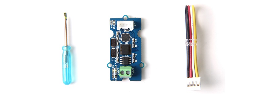
Partlist
Features
- Uart to CAN Bus
- Work with Arduino/BeagleBone board/Pi or any MCU that integrated with UART.
- AT command
- Up to 115200 Uart baud rate (default 9600)
- Up to 1Mb/s CAN Bus baud rate (default 500k)
- TX and RX led indicator
- 4pin HY connector
- 3.3 / 5V working voltage
- Easy-to-use Arduino library
- Small size: 20x40 mm
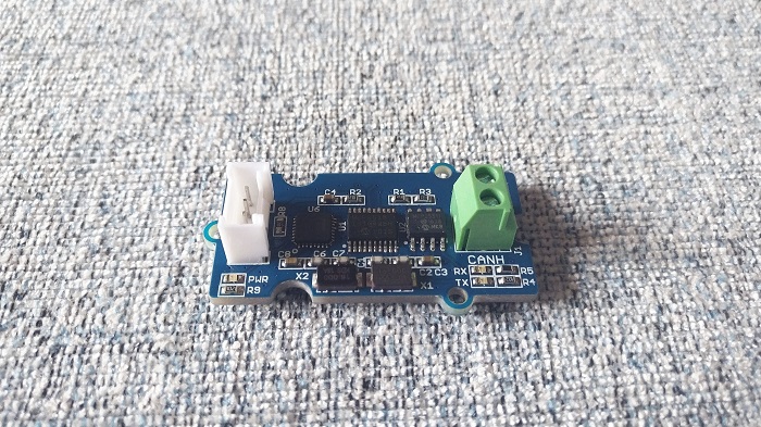
Hardware Overview
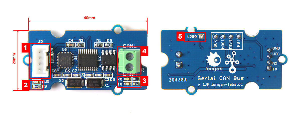
- 4 pin 2.0mm Grove Connector
- Power and status led indicator
- Send and Recv led indicator
- 3.5mm terminal to connect to CAN Bus (CAN_H & CAN_L)
- 120Ω registor.
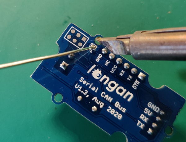
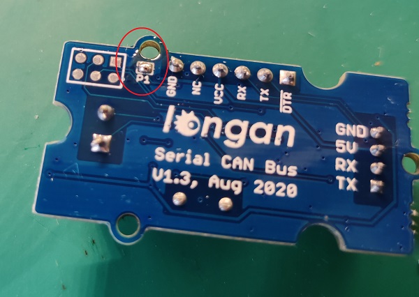
120 Terminal resistor
If you need the 120Ω terminal resistor, you need a soldering iron, as shown below:
Work at 3.3V
The module is working at 5V most of time. If you want it to work at 3.3V IO, please try:
V1.3 Version
V1.3 work well at 3.3V IO and VCC.
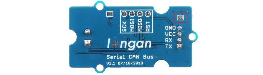
V1.1 and V1.2 Verstion
There's a jumper on the back side, please connect the pads together with a soldering iron. And VCC must connect to 5V.
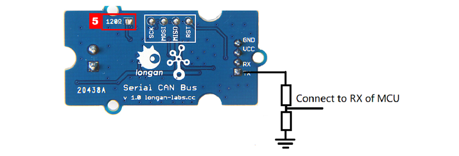
V1.0 Version
Please try as below, and please note that VCC till need to connect to 5V.
AT Command
You can achieve the complete function of this Serial CAN Bus module with only a few AT command.
| CMD | Description |
|---|---|
| +++ | Switch from Normal mode to Config mode |
| AT+S=[value] | Set serial baud rate |
| AT+C=[value] | Set CAN Bus baud rate |
| AT+M=[N][EXT][value] | Set mask |
| AT+F=[N][EXT][value] | Set filter |
| AT+Q | Switch to Normal Mode |
Note
All of the cmd should end with '\n' except +++
Set the Baud Rate of UART
You can set the baud rate of UART of the module with this command. There're 5 rates available, up to 115200 b/s.
AT+S=[value]
| value | 0 | 1 | 2 | 4 |
|---|---|---|---|---|
| baud rate(b/s) | 9600 | 19200 | 38400 | 115200 |
Note
Default is 9600
Eg: Set serial baud rate to 115200
AT+S=4
Note
Please DON'T send AT+S=3 to the board, otherwise it may become brick.
Respose
OK or ERROR
Note
If you are using the SoftwareSerial of Arduino, please don't set the baud rate to 115200.
Set CAN Bus Baudrate
You can use this command to set the rate of CAN Bus, there's 18 rates available. Normally, if you want to hack your vehicle, 500k is the right one.
AT+C=[value]
| value | 01 | 02 | 03 | 04 | 05 | 06 | 07 | 08 | 09 | 10 | 11 | 12 | 13 | 14 | 15 | 16 | 17 | 18 |
|---|---|---|---|---|---|---|---|---|---|---|---|---|---|---|---|---|---|---|
| rate(kb/s) | 5 | 10 | 20 | 25 | 31.2 | 33 | 40 | 50 | 80 | 83.3 | 95 | 100 | 125 | 200 | 250 | 500 | 666 | 1000 |
Tip
Default is 500K
Eg: Set CAN BUS baud rate to 50K
AT+C=08
Respose
OK or ERROR
Set Mask
There're 2 Mask for the module, Mask0 and Mask1.
AT+M=[N][EXT][value]
N:
- 0: Mask0
- 1: Mask1
EXT:
- 0: Standard Frame
- 1: Extended Frame
value:
Neeed 8 bit of character, hexadecimal.
Eg: Set Mask1 to 0x3DF, standard frame:
AT+M=[1][0][000003DF]
Respose
OK or ERROR
Set Filt
There're 6 Mask for the module, Filt0 ~ Filt5
AT+F=[N][EXT][value]
N:
| N | 0 | 1 | 2 | 3 | 4 | 5 |
|---|---|---|---|---|---|---|
| Filt | Filt0 | Filt1 | Filt2 | Filt3 | Filt4 | Filt5 |
EXT:
- 0: Standard Frame
- 1: Extended Frame
value:
Neeed 8 bit of character, hexadecimal.
Eg: Set Filt3 to 0x2C, standard frame:
AT+F=[1][0][0000002C]
Respose
OK or ERROR
Working Mode
When the module working on Working mode (default mode), you can send and recevie data from CAN Bus.
Send
You should send 14 byte of data per frame. Defined as below,
| bit | 0 | 1 | 2 | 3 | 4 | 5 | 6 | 7 | 8 | 9 | 10 | 11 | 12 | 13 |
|---|---|---|---|---|---|---|---|---|---|---|---|---|---|---|
| define | ID3 | ID2 | ID1 | ID0 | EXT | RTR | DTA0 | DTA1 | DTA2 | DTA3 | DTA4 | DTA5 | DTA6 | DTA7 |
- ID0~ID3: CAN ID
- EXT: 0 for standard frame, 1 for extended frame
- RTR: 0 for standard frame, 1 for remote frame
- DTA0~DTA7: 8 byte of data
Eg.
Send {1, 2, 3, 4, 5, 6, 7, 8} to ID:0x3DC, Standard frame:
{0, 0, 3, 0xDC, 0, 0, 1, 2, 3, 4, 5, 6, 7, 8}
Recv
You will get 12 byte of data per frame. Defined as below,
| bit | 0 | 1 | 2 | 3 | 4 | 5 | 6 | 7 | 8 | 9 | 10 | 11 |
|---|---|---|---|---|---|---|---|---|---|---|---|---|
| define | ID3 | ID2 | ID1 | ID0 | DTA0 | DTA1 | DTA2 | DTA3 | DTA4 | DTA5 | DTA6 | DTA7 |
- ID0~ID3: CAN ID
- DTA0~DTA7: 8 byte of data
Work with Arduino
120Ω Terminal Resistor
As there're only 2 serial can bus device, it need the 120Ω resistor, there's a P1 on the back side, please solder P1 to get the 120Ω resistor, as shown below,
Hardware Connection
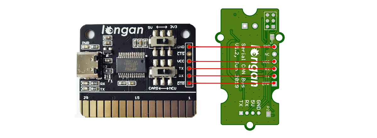
There are 4 pins on the board, they are:
| Pin Name | Function | Color |
|---|---|---|
| TX | TX of UART | Yellow |
| RX | RX of UART | White |
| 5V | VCC, connect to 5V (V1.0/V1.1/V1.2/V1.3) or 3.3V(only V1.3 or after) | Red |
| GND | Ground | Black |
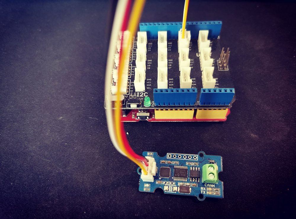
If you got a Base Shield from Seeedstudio, the connection is easy, like below,
If there's no Base Shield for you, you need some dupont cable, and connect TX/RX to the IO of your Arduino, here we connect TX/RX to D2/D3:
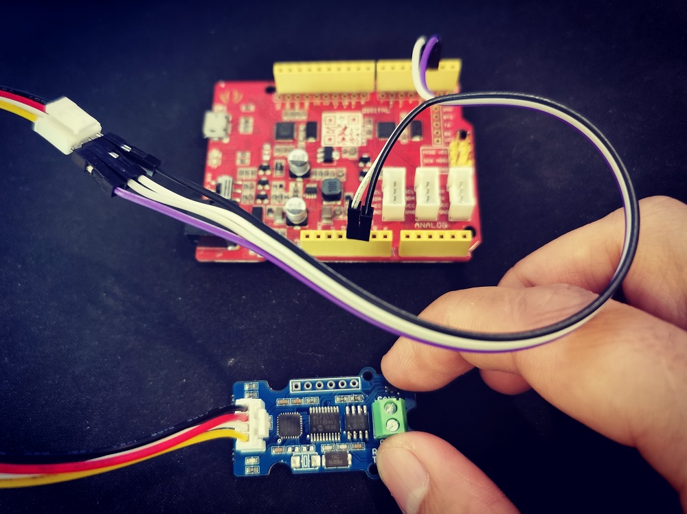
Note
Not all pins on the Mega and Mega 2560 support change interrupts, so only the following can be used for RX: 10, 11, 12, 13, 14, 15, 50, 51, 52, 53, A8 (62), A9 (63), A10 (64), A11 (65), A12 (66), A13 (67), A14 (68), A15 (69).
Software
We provide an library for Aruino Software Serial.
Please download it at Github
There're many examples for the library, which is consist of,
- send - How to send a frame to CAN Bus
- recv - How to recv a frame from CAN Bus
- debug - debug mode, you can send a cmd to the module
- set_can_baudrate - set can bus baudrate
- set_mask_filt - set mask and filt of the module
Test the board
Here we make an example to show you how the board work with CAN Bus.
The connection like below, here we use Seeeduino + Serial CAN bus module as the receiver, and a USB2Uart module + Serial CAN bus module as sender.
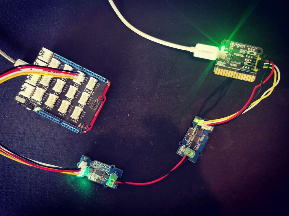
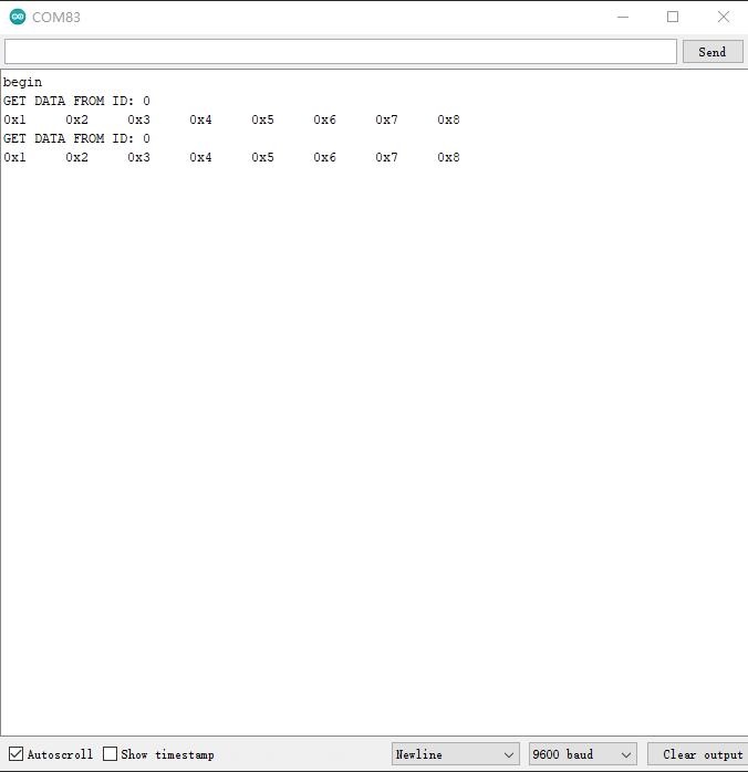
If you send the command of sending frame to the USB2Uart module, open the Arduino serial monitor, you will get data from CAN Bus.
Get data from a Vehicle
We can use Serial CAN Bus Module to get data from a vehicle, we take the vehicle speed for an example here.
You can use our products to read data from cars. Here we provide a simple example by which you can read the speed and revs from a car. This is the OBD-based PIDs protocol. Regarding the deeper technology of OBD, we can't provide support at present. You may need to have some understanding of the car's protocol. After all, we are more of a hardware supplier.
The interface of OBD is as follows,
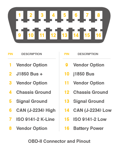
There're 4 pins we need to connect.
| OBD Pin | CANBed PIN |
|---|---|
| 6. CAN(J-2234) High | CANH |
| 14. CAN(J-2234) Low | CANL |
The default baud rate of the board is 9600, we need to set the baud rate higher, we set it to 38400. Please upload below code to your Arduino board to modify the baudrate to 38400.
#include <Serial_CAN_Module.h>
#include <SoftwareSerial.h>

Serial_CAN can;

#define can_tx  2       // tx of serial can module, the yellow cable
#define can_rx  3       // rx of serial can module, the white cable

void setup()
{
    Serial.begin(9600);
    while(!Serial);
    Serial.println("START to set the serial baud rate...");
    can.begin(can_tx, can_rx, 9600);      // set this baudrate to the current baudrate

    if(can.baudRate(SERIAL_RATE_38400))     // SERIAL_RATE_9600, SERIAL_RATE_19200, SERIAL_RATE_38400
    {
        Serial.println("set baud rate ok");
    }
    else
    {
        Serial.println("set baud rate fail");
    }
}


void loop()
{

}
Then we have to set the mask and filter, please upload below code to your Arduino,
#include <Serial_CAN_Module.h>
#include <SoftwareSerial.h>

#define STANDARD_CAN_11BIT      1       // That depands on your car. some 1 some 0.

Serial_CAN can;

#define can_tx  2           // tx of serial can module connect to D2
#define can_rx  3           // rx of serial can module connect to D3

#define PID_ENGIN_PRM       0x0C
#define PID_VEHICLE_SPEED   0x0D
#define PID_COOLANT_TEMP    0x05

#if STANDARD_CAN_11BIT
#define CAN_ID_PID          0x7DF
#else
#define CAN_ID_PID          0x18db33f1
#endif

#if STANDARD_CAN_11BIT
unsigned long mask[4] =
{
    0, 0x7FC,                // ext, maks 0
    0, 0x7FC,                // ext, mask 1
};

unsigned long filt[12] =
{
    0, 0x7E8,                // ext, filt 0
    0, 0x7E8,                // ext, filt 1
    0, 0x7E8,                // ext, filt 2
    0, 0x7E8,                // ext, filt 3
    0, 0x7E8,                // ext, filt 4
    0, 0x7E8,                // ext, filt 5
};

#else
unsigned long mask[4] =
{
    1, 0x1fffffff,               // ext, maks 0
    1, 0x1fffffff,
};

unsigned long filt[12] =
{
    1, 0x18DAF110,                // ext, filt
    1, 0x18DAF110,                // ext, filt 1
    1, 0x18DAF110,                // ext, filt 2
    1, 0x18DAF110,                // ext, filt 3
    1, 0x18DAF110,                // ext, filt 4
    1, 0x18DAF110,                // ext, filt 5
};
#endif


void setup() {
    Serial.begin(115200);
    while(!Serial);

    can.begin(can_tx, can_rx, 38400);      // tx, rx

    Serial.println(can.canRate(CAN_RATE_500) ? "set can rate ok" : "set can rate fail");
    Serial.println(can.setMask(mask) ? "set mask ok" : "set mask fail");
    Serial.println(can.setFilt(filt) ? "set filt ok" : "set filt fail");
}

void loop() {

}
Upload the following code to the development board, then open the serial monitor, you get the speed from the car now.
#include <Serial_CAN_Module.h>
#include <SoftwareSerial.h>

#define STANDARD_CAN_11BIT      1       // That depands on your car. some 1 some 0.

Serial_CAN can;

#define can_tx  2           // tx of serial can module connect to D2
#define can_rx  3           // rx of serial can module connect to D3

#define PID_ENGIN_PRM       0x0C
#define PID_VEHICLE_SPEED   0x0D
#define PID_COOLANT_TEMP    0x05

#if STANDARD_CAN_11BIT
#define CAN_ID_PID          0x7DF
#else
#define CAN_ID_PID          0x18db33f1
#endif


void sendPid(unsigned char __pid) {
    unsigned char tmp[8] = {0x02, 0x01, __pid, 0, 0, 0, 0, 0};

#if STANDARD_CAN_11BIT
    can.send(CAN_ID_PID, 0, 0, 8, tmp);   // SEND TO ID:0X55
#else
    can.send(CAN_ID_PID, 1, 0, 8, tmp);   // SEND TO ID:0X55
#endif
}

bool getSpeed(int *s)
{
    sendPid(PID_VEHICLE_SPEED);
    unsigned long __timeout = millis();

    while(millis()-__timeout < 1000)      // 1s time out
    {
        unsigned long id  = 0;
        unsigned char buf[8];

        if (can.recv(&id, buf)) {                // check if get data

            if(buf[1] == 0x41)
            {
                *s = buf[3];
                return 1;
            }
        }
    }

    return 0;
}

void setup() {
    Serial.begin(115200);
    while(!Serial);
    can.begin(can_tx, can_rx, 38400);
    Serial.println("begin");
}

void loop() {

    int __speed = 0;
    int ret = getSpeed(&__speed);
    if(ret)
    {
        Serial.print("Vehicle Speed: ");
        Serial.print(__speed);
        Serial.println(" kmh");
    }
    delay(500);
}
Working Standalone
For V1.2 and after, you can program the on-board MCU (Atmega168PA) with Arduino IDE.
First, you need a USB to Serial board, something like the Programmer Card
Here we will take Programmer Card as an example:
Then, we need to setup your Arduino IDE.
Start the Arduino IDE.
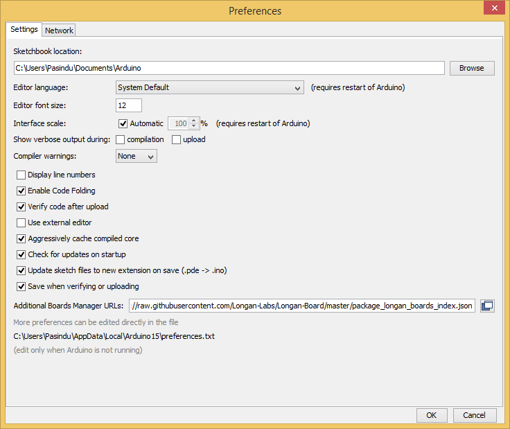
Copy and paste the link below into the Additional Boards Manager URLs option in the Arduino IDE preferences (File > Preferences).
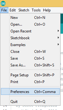
https://raw.githubusercontent.com/Longan-Labs/Longan-Board/master/package_longan_boards_index.json
The Longan AVR boards supplied package includes supports for Longan Card, Carduino 328, Carduino 32U4.
Once done, click OK button to save the new preference settings.
Now open the Boards Manager by navigating to the Tools -> Board menu.
Select All from the Type drop-down menu. Then type longan in the top search bar. While typing, you will see the Longan AVR package.
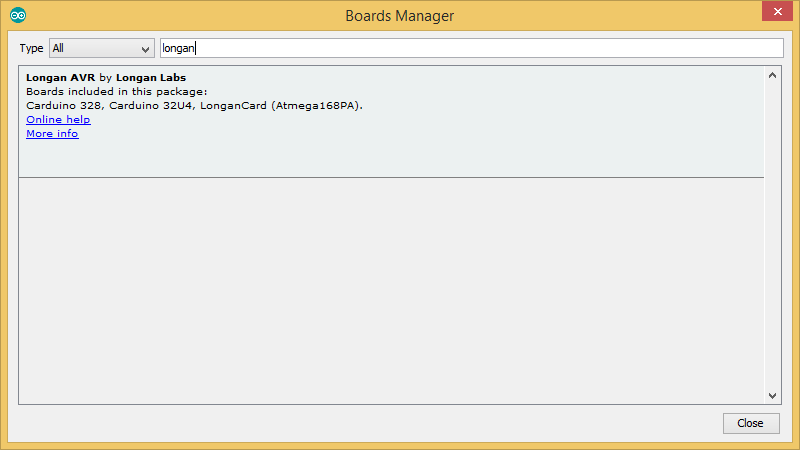
Click on the Longan AVR by Longan Labs and then click on Install button.
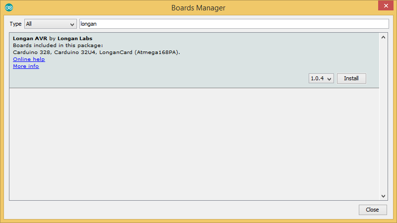
Once installed, close the Boards Manager window.
Then you can find Serial CAN Bus Module in the board list.
FAQ
The RX and TX leds light up instead of blinking
- Please check the baudrate of CAN Bus
- If the serial can bus module is in the end, the 120Ω terminal resistor is needed, please soder P1 on the back side of PCBA
Don't work with Arduino Mega
Not all pins on the Mega and Mega 2560 support change interrupts, so only the following can be used for RX: 10, 11, 12, 13, 14, 15, 50, 51, 52, 53, A8 (62), A9 (63), A10 (64), A11 (65), A12 (66), A13 (67), A14 (68), A15 (69).
How to find the tech support
Please contact support@longan-labs.cc for technical support. Our technical support engineer will usually reply you within 24 hours on working days. In order to get faster support, we hope that when you send us an email, you need to include at least the following content,
- When and how to buy the product
- Product version information
- Take a high-definition picture of the product you use, including the connection
- Describe in detail the problem you encountered and what kind of help you would like to get