OBD-II CAN BUS GPS DEV KIT
Introduction

The OBD Ⅱ Slaver allows you to hack your vehicle with the integrated OBD port and output all the data via serial interface. It supports the CAN bus protocol, integrates micro SD card slot. On top of that, with the help of a build-in Atmega32U4 (RP2040 for V2), it's compatible with arduino. Which means you can code it like a ardunio, then just plug it into your car's OBD port, you will get the output data via the Type C USB port or you can store all the data into your micro-SD card (TF card), easy-peasy.
This Serial CAN Bus module is based on MCP2551 and MCP2515, which can provide can baud rate from 5kb/s to 1Mb/s.
One more thing, we integrate the GPS module, you can even track your car with this fantastic little module. It is obviously that you will love it, happy hacking!
Version Track:
- V1.0 - Original version, Atmega32U4 MCU.
- V2.0 - Change MCU to RP2040
CAN BUS PRODUCTS LIST OF LONGAN LABS

We have made a lot of can bus products, you can get more information through the following list, so as to choose a product suitable for you.
| PRODUCT NAME | LINK | PRICE | MCU | CHIP | PROTOCOL |
|---|---|---|---|---|---|
| Serial CAN Bus Module | LINK | $19.9 | ATMEGA168PA | MCP2515 | CAN2.0 |
| I2C CAN Bus Module | LINK | $19.9 | ATMEGA168PA | MCP2515 | CAN2.0 |
| OBD-II Serial CAN Bus Dev Kit | LINK | $20.9 | ATMEGA168PA | MCP2515 | CAN2.0 |
| OBD-II CAN Bus GPS Dev Kit | LINK | $29.9 | ATMEGA32U4(RP2040 for V2) | MCP2515 | CAN2.0 |
| OBD-II CAN Bus Basic Dev Kit | LINK | $24.9 | ATMEGA32U4(RP2040 for V2) | MCP2515 | CAN2.0 |
| CAN-FD Shield | LINK | $19.9 | NO MCU | MCP2517FD | CAN-FD |
| CAN Bus Shield | LINK | $9.9 | NO MCU | MCP2515 | CAN2.0 |
| CANBed | LINK | $24.9 | ATMEGA32U4 | MCP2515 | CAN2.0 |
| CANBed-FD | LINK | $29.9 | ATMEGA32U4 | MCP2517FD | CAN-FD |
| CANBed M4 | LINK | $49.9 | ATSAME51 | - | CAN-FD |
| OBD-II RF Dev Kit | LINK | $19.9 | ATmega168PA | MCP2515 | CAN2.0 |
Note
The above price may not be the latest price, please refer to the price on the product page.
Features
- ODB Ⅱ port
- Uart to CAN Bus communication
- Build-in Atmega32U4 (RP2040 for V2)
- Integraded GPS module
- Integraded Micro-SD(TF) card
- AT command support
- Up to 115200 Uart baud rate (default 9600)
- Up to 1Mb/s CAN Bus baud rate
- TX and RX led indicator
- Easy-to-use Arduino library
Specifications
| Parameter | Value |
|---|---|
| MCU | Atmega32U4 (with Arduino Leonardo bootloader) / RP2040 for V2 |
| Clock Speed | 16MHz |
| Flash Memory | 32KB |
| SRAM | 2.5KB |
| EERROM | 1KB |
| Operate Voltage | 5V |
| Input Interface | OBD-II |
| Output Interface | USB Type C |
Hardware Overview
Part List
- OBD-II Slaver(Base board) x 1
- GPS Board x 1
- Plastic Case x 1
- Screw Driver x 1

Pin out
Base Board

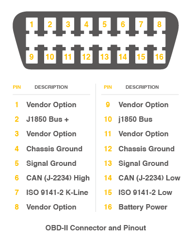
1.OBD-II Connector:
On-board diagnostics (OBD) is an automotive term referring to a vehicle's self-diagnostic and reporting capability. OBD-II is an improvement over OBD-I in both capability and standardization. The OBD-II standard specifies the type of diagnostic connector and its pinout.
2.Reset Button:
Reset the on-board Atmega chip, please note that the button had been canceled in the latest version.
3.78L05:
Provide a stable 5V to the whole system.
4.Atmega32U4:(RP2040 for V2)
The master of the entire module, mainly used to store data on the TF card or transfer data to the computer through the type C cable. In addition, since it's arduino compatible, you can use it to implement some simple controls, such as triggering a buzzer alarm when the speed exceeds a certain value.
5.MCP2515:
Microchip Technology’s MCP2515 is a stand-alone Controller Area Network (CAN) controller that implements the CAN specification, version 2.0B. It is capable of transmitting and receiving both standard and extended data and remote frames. The MCP2515 has two acceptance masks and six acceptance filters that are used to filter out unwanted messages, thereby reducing the host MCUs overhead. The MCP2515 interfaces with microcontrollers (MCUs) via an industry standard Serial Peripheral Interface (SPI).
6.MCP2551
High-Speed CAN Transceiver:The MCP2551 is a high-speed CAN, fault-tolerant device that serves as the interface between a CAN protocol controller and the physical bus. Typically, each node in a CAN system must have a device to convert the digital signals generated by a CAN controller to signals suitable for transmission over the bus cabling (differential output). It also provides a buffer between the CAN controller and the high-voltage spikes that can be generated on the CAN bus by outside sources (EMI, ESD, electrical transients, etc.).
7.2x8Pin Female Header for GPS module
See the GPS section for specific pin definitions.
Attention
It should be noted that when assembling the GPS module, please align the white triangle on the development board and the module, otherwise the GPS module may be damaged.
8.CAN RX/TX Indicator
9.Power LED
A.Micro USB connector for programming
B.User LED, connect to D13 (D18 for RP2040 version)
C.TF Card slot
D.120Ω resister
ISO 11898 requires a cable with a nominal impedance of 120 Ω; therefore, you should use 120 Ω resistors for termination. If you place multiple devices along the cable, only the devices on the ends of the cable need termination resistors. Figure 1 shows an example of how to terminate a high-speed network.

So if you use this slaver on the end of the CAN bus, you need to solder a 120Ω resister between the two pad, if not just leave them alone. For more detail about the CAN bus protocol, please refer to the NI CAN Physical Layer and Termination Guide
E.ICSP pads for burning bootloader
GPS Board

1.GPS Antenna

2.2x8Pin header
3. GPS module
4. External Antenna Port
NEO-6 modules are designed for use with passive and active13 antennas.
| Parameter | Specification | |
|---|---|---|
| Antenna Type | Passive and active antenna | |
| Minimum gain | 15 dB (to compensate signal loss in RF cable) | |
| Maximum gain | 50 dB | |
| Maximum noise figure | 1.5 dB |
Arduino IDE Setup for V2 (RP2040 version)
If you are using the V1 (Atmega32U4 version), please skip this chapter.
First download the Arduino IDE from https://www.arduino.cc/en/Main/Software. Arduino IDE can be installed and run on Windows, Linux, and Mac OS X operating systems. Download the installer or zip file (Windows only) and install (if you have the zip file, extract it to your Windows computer’s hard drive) it on your operating system.
Once finished, start the Arduino IDE.
Copy and paste the link below into the Additional Boards Manager URLs option in the Arduino IDE preferences (File > Preferences).
https://raw.githubusercontent.com/Longan-Labs/Longan-RP2040/main/package_rp2040_index.json
Once done, click OK button to save the new preference settings.
Now open the Boards Manager by navigating to the Tools -> Board menu.
Select All from the Type drop-down menu. Then type longan in the top search bar. While typing, you will see the Longan RP2040 Boards package.
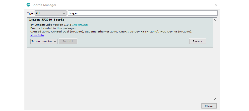
Click on the Longan RP2040 Boards by Longan Labs and then click on Install button.
Once installed, close the Boards Manager window.
Assembly and Hardware Connection
Assembly
It is assembled when you get the development board. If you disassemble it, you can reassemble it by following the steps.
Step 1.
Please check each part.
Step 2.
Mount the base board to the bottom housing.

Step 3.
Insert the GPS board on the baseboard.

Attention
When inserting the GPS board, be careful to align the white triangles of the GPS and Base boards.
Step 4.
Close the top cover and fix it with screws.

Get data from a Vehicle
We can use this kit to get data from a vehicle, we take the vehicle speed for an example here.
You can use our products to read data from cars. Here we provide a simple example by which you can read the speed and revs from a car. This is the OBD-based PIDs protocol. Regarding the deeper technology of OBD, we can't provide support at present. You may need to have some understanding of the car's protocol. After all, we are more of a hardware supplier.
The interface of OBD is as follows,
Upload the following code to the development board, then open the serial monitor, you get the speed from the car now.
#include <SPI.h>
#include "mcp_can.h"

/* Please modify SPI_CS_PIN to adapt to different baords.

   CANBed V1        - 17
   CANBed M0        - 3
   CAN Bus Shield   - 9
   CANBed 2040      - 9
   CANBed Dual      - 9
   OBD-2G Dev Kit   - 9
   Hud Dev Kit      - 9
*/

#define SPI_CS_PIN  9

MCP_CAN CAN(SPI_CS_PIN);                                    // Set CS pin

#define PID_ENGIN_PRM       0x0C
#define PID_VEHICLE_SPEED   0x0D
#define PID_COOLANT_TEMP    0x05

#define CAN_ID_PID          0x7DF

void set_mask_filt()
{
    // set mask, set both the mask to 0x3ff

    CAN.init_Mask(0, 0, 0x7FC);
    CAN.init_Mask(1, 0, 0x7FC);

    // set filter, we can receive id from 0x04 ~ 0x09

    CAN.init_Filt(0, 0, 0x7E8);
    CAN.init_Filt(1, 0, 0x7E8);

    CAN.init_Filt(2, 0, 0x7E8);
    CAN.init_Filt(3, 0, 0x7E8);
    CAN.init_Filt(4, 0, 0x7E8);
    CAN.init_Filt(5, 0, 0x7E8);
}

void sendPid(unsigned char __pid) {
    unsigned char tmp[8] = {0x02, 0x01, __pid, 0, 0, 0, 0, 0};
    CAN.sendMsgBuf(CAN_ID_PID, 0, 8, tmp);
}

bool getSpeed(int *s)
{
    sendPid(PID_VEHICLE_SPEED);
    unsigned long __timeout = millis();

    while(millis()-__timeout < 1000)      // 1s time out
    {
        unsigned char len = 0;
        unsigned char buf[8];

        if (CAN_MSGAVAIL == CAN.checkReceive()) {                // check if get data
            CAN.readMsgBuf(&len, buf);    // read data,  len: data length, buf: data buf

            if(buf[1] == 0x41)
            {
                *s = buf[3];
                return 1;
            }
        }
    }

    return 0;
}

const int pinPwrCtrl = 12;          // for RP2040 verison
//const int pinPwrCtrl = A3;        // for Atmaega32U4 version

void setup() {
    Serial.begin(115200);
    while(!Serial);

    pinMode(pinPwrCtrl, OUTPUT);        // Enable power for GPS and CAN Bus
    digitalWrite(pinPwrCtrl, HIGH);

    while (CAN_OK != CAN.begin(CAN_500KBPS)) {             // init can bus : baudrate = 500k
        Serial.println("CAN init fail, retry...");
        delay(100);
    }
    Serial.println("CAN init ok!");
    set_mask_filt();
}

void loop() {

    int __speed = 0;
    int ret = getSpeed(&__speed);
    if(ret)
    {
        Serial.print("Vehicle Speed: ");
        Serial.print(__speed);
        Serial.println(" kmh");
    }
    delay(500);
}

// END FILE
GPS Usage
The GPS Module use serial port to output the GPS data, you just need to connect this module to your PC via the USB type C cable, using any serial tool such as putty, you will be able to get the GPS data.
Please upload below code to the board,
const int pinPwrCtrl = 12;      // for RP2040 verison
//const int pinPwrCtrl = A3;      // for Atmaega32U4 version
void setup()
{
    pinMode(pinPwrCtrl, OUTPUT);
    digitalWrite(pinPwrCtrl, HIGH);         // power on

    Serial.begin(9600);
    Serial1.begin(9600);
}


void loop()
{
    while(Serial1.available())
    {
        Serial.write(Serial1.read());
    }
}

// END FILE
The open your serial monitor,

CAN BUS Usage
Arduino Code
We provide an arduino library for the dev board.
There're many examples for the library, which is consist of,
- send - How to send a frame to CAN Bus
- recv - How to recv a frame from CAN Bus
HOW TO GET DATA FROM THE CAR
There's an OBDII_PIDs sketch in the library. Open the sketch and upload it to the board.
Then open the serial monitor, input a PID, then you will get reponse from vehicle, the input should be end with '\n'.
Reference
- Base board eagle file for Atmega32U4 version
- [Base board eagle file for RP2040 version]
- GPS borad eagle file
- Arduino Library
- NEO-6 Datasheet