Line Finder Card
Introduction
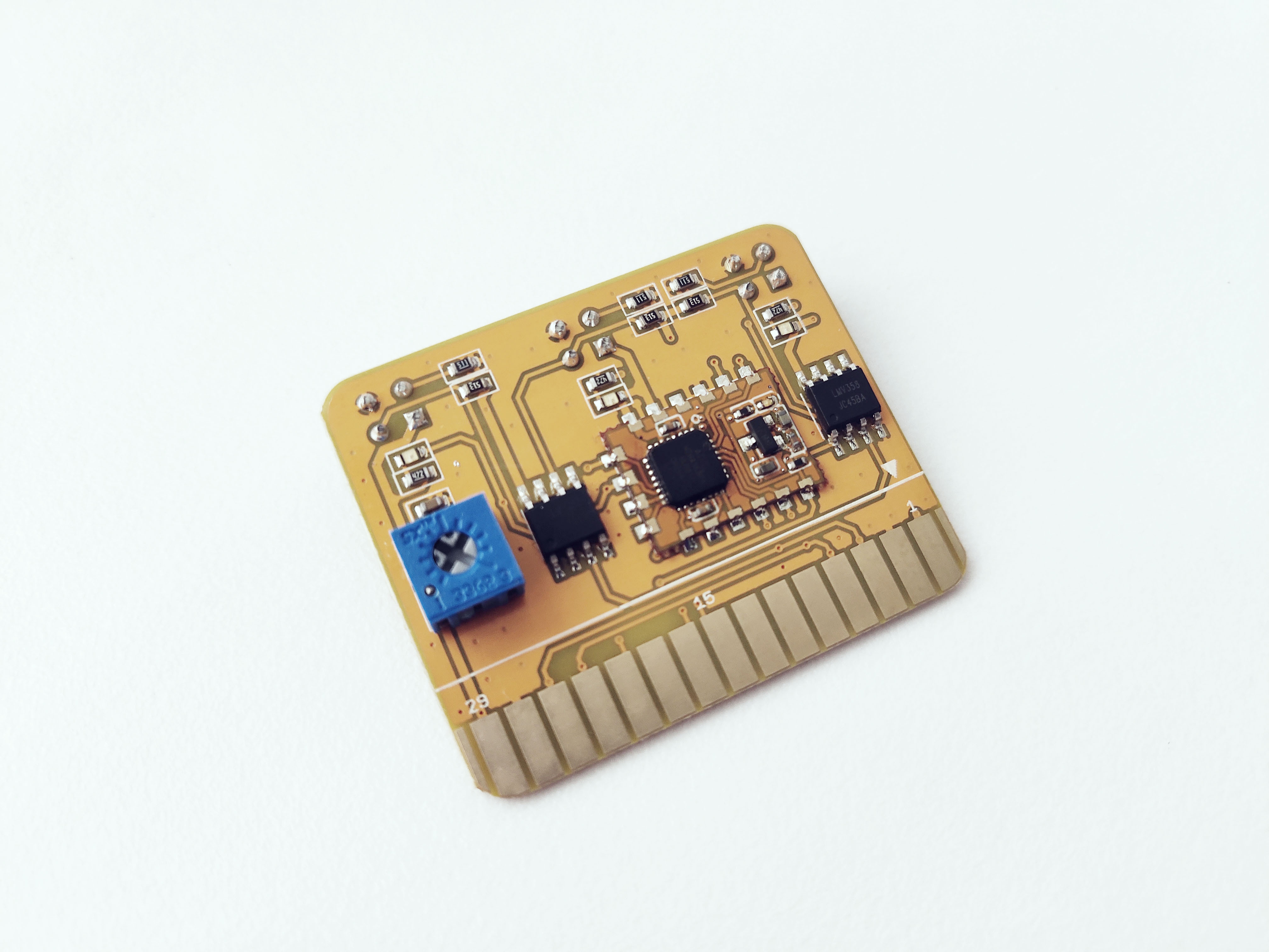
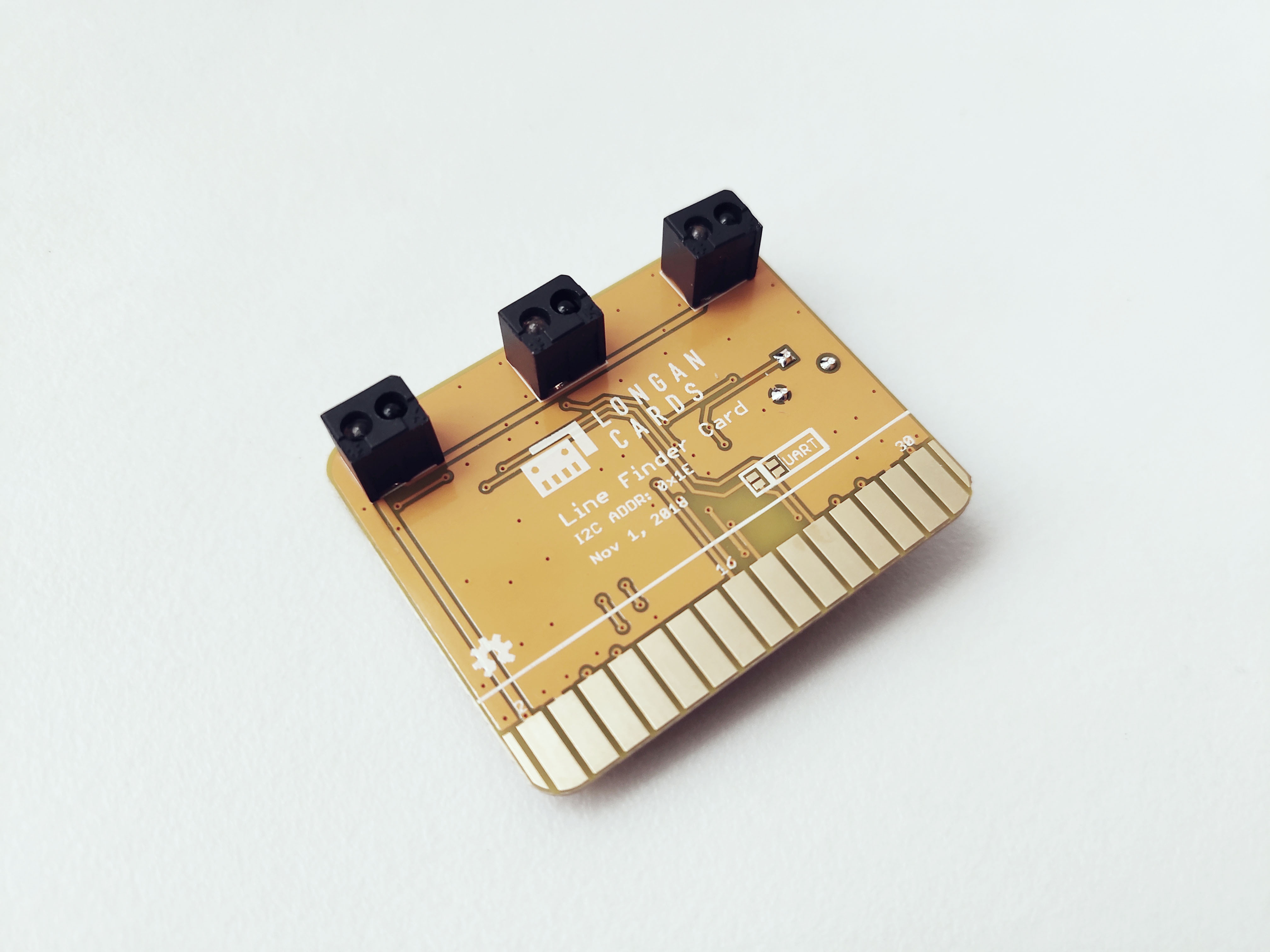
The Longan Line Finder Card features MV358 comparator, and it is ideal for building a line following robots. On the back of the Line Finder Card, there are three sets of sensors consists of IR emitting LED and an IR sensitive phototransistor. Each sensor is capable of detecting a black line on the white background or a white line on the black background.
For your convenience, use the following to determine your position:
- When the digital signal is HIGH, it indicates you are on the black line.
- When the digital signal is LOW, it indicates you are on the white line
Why three sets of IR emitting LED and an IR sensitive phototransistor?
-
The left two sensors (as a single sensor unit) capable of detecting the left edge of the black or white line (usually the line should be at least 1" of width) and adjust the motors accordingly.
-
The right sensor unit capable of detecting the right edge of the black or white line and adjust the motors accordingly.
-
The middle sensor unit capable of detecting the center of the black and white line and adjust the motors accordingly.
The trim-pot on the top of the card can be used to adjust the detecting range of the Line Finder Card.
Specifications
- Easy to use
- Integrated three LED indicators
- Adjustable detecting range.
- Power supply: 5V DC
- Digital output mode: TTL (High when black is detected, Low when white is detected)
- Comparator: LMV358
- Photo reflective diode: RS-06WD
I2C Address
The default I2C address is printed on the back side of the card which is 0x1E. However, you can change it to a different address with the card firmware (Read our wiki for how to change the default I2C address of a card.).
Pins
The edge connector (gold fingers) has total of 30 contacts (each side has 15 contacts).
On the front side of the Line Finder Card, a white arrow is printed near the edge connector indicates the pin #1. You can find some pin numbers printed on the edge connector itself (1, 15, and 29). You can count the pin numbers starting with 1 and count by twos from right to left would be 1, 3, 7, 9, 11, 15, 17, 19, 21, 23, 27, and 29. Notice that all the counts are odd numbers.
On the back side of the Line Finder Card, you also can find some pin numbers printed on the edge connector itself (2, 16, and 30). You can count the pin numbers starting with 2 and count by twos from left to right would be 2, 4, 6, 8, 10, 12, 14, 16, 18, 20, 22, 24, 26, 28 and 30. Notice that all the counts are even numbers.
Among the 30 pins, following pins can be used for I2C communication.
- SDA: Digital I/O, I2C bus serial bidirectional data line (Front: pin #5, #25 / Back: pin #6, #26)
- SCL: Digital Input, I2C bus serial clock input (Front: pin #7, #23 / Back: pin #8, #24)
Also, following pins connect with the common power bus of the board.
- VCC: Power supply (Front: pin #1, #29 / Back: pin #2, #30)
- GND: To be connected to the system ground (Front: pin #3, #27 / Back: pin #4, #28)
How to Use
The Line Finder Card is ideal to use with the Longan Car Board.
When you plug, the white arrow head printed on the card should be pointing toward the white arrow head printed near the edge connector slot of the board. Once plugged, it can communicate with the Carduino through the I2C bus line of the board. It will also connect to the common power bus of the board.
Example 1
Coming soon.