IR Receiver Card
Introduction
The IR Receiver card allows you to detect infrared (E.g., IR signal from a remote controller). There is an IR detector on the IR Receiver card which is used to get the infrared light emitted by the Infrared Emitter. It can detect a modulated IR signal at 38 KHz. The distance between the IR Receiver card and the IR source should be less than 10 meters.
NOTE: The IR Receiver Card supports two wire I2C bus interface.
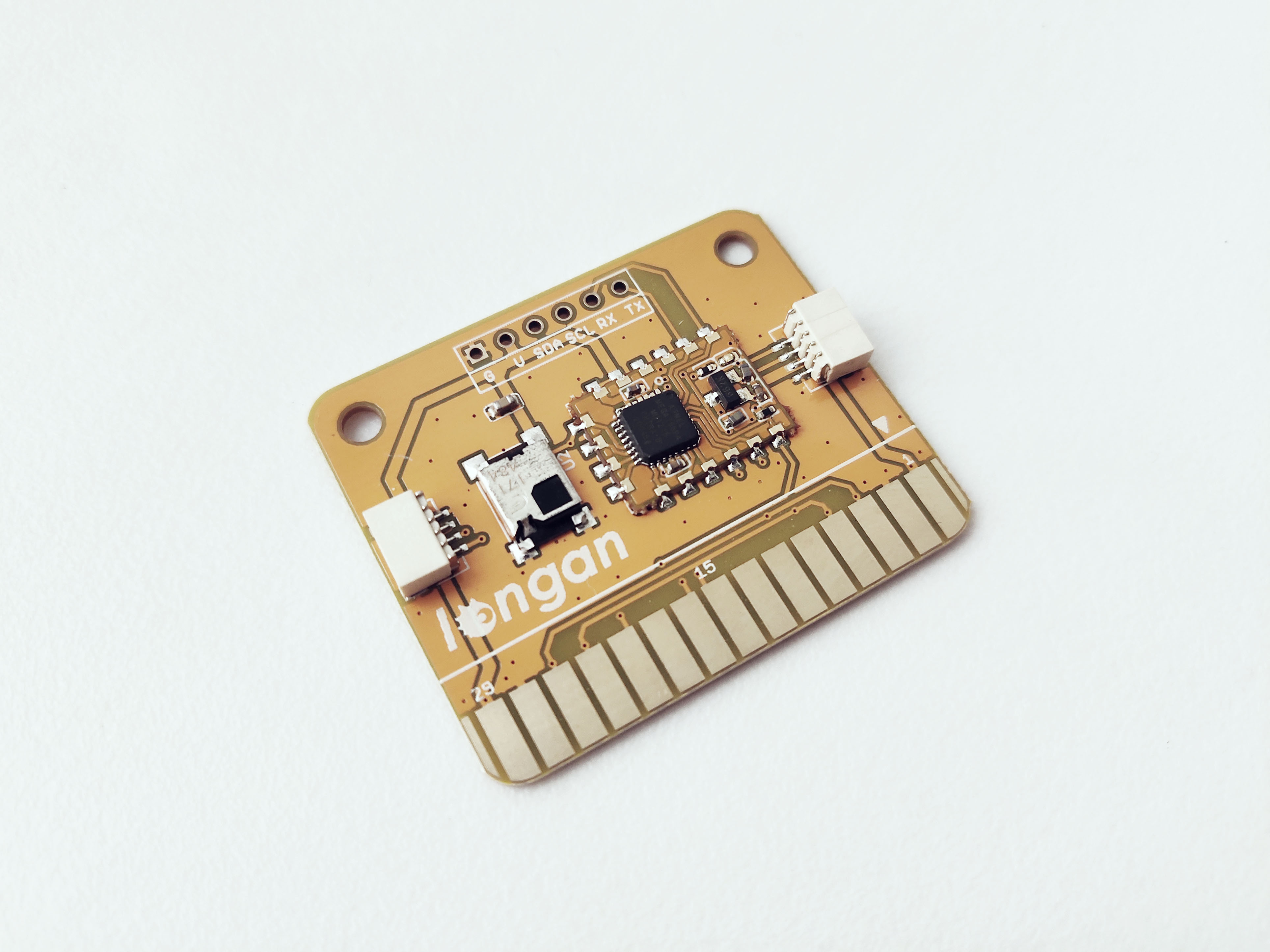
The front of the IR Receiver Card has following things.
- RS-171 IR receiver
- 30 gold fingers (30 pin edge connector) - allows you to plug the card into any edge connector slot of a Longan board.
- ATmega 168PA microprocessor - runs card firmware.
- LED indicator – flashes when Carduino read/write data from/to the card through I2C.
- Two 4 pin SH1.0 connectors - allows you to connect MCUs or cards which support I2C communication protocol with dupont cables.
Specifications
- Voltage: 5V
- Range: About 10m
- Supports two wire I2C bus interface
I2C Address
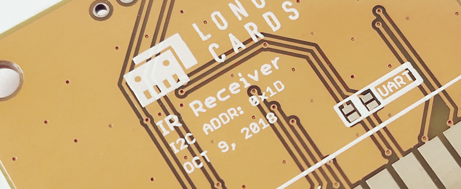
The default I2C address is printed on the back side of the card which is 0x1D. However, you can change it to a different address with the card firmware (Read our wiki for how to change the default I2C address of a card.).
Pins
The edge connector (gold fingers) has total of 30 contacts (each side has 15 contacts).
On the front side of the IR Receiver card, a white arrow is printed near the edge connector indicates the pin #1. You can find some pin numbers printed on the edge connector itself (1, 15, and 29). You can count the pin numbers starting with 1 and count by twos from right to left would be 1, 3, 7, 9, 11, 15, 17, 19, 21, 23, 27, and 29. Notice that all the counts are odd numbers.
On the back side of the IR Receiver card, you also can find some pin numbers printed on the edge connector itself (2, 16, and 30). You can count the pin numbers starting with 2 and count by twos from left to right would be 2, 4, 6, 8, 10, 12, 14, 16, 18, 20, 22, 24, 26, 28 and 30. Notice that all the counts are even numbers.
Among the 30 pins, following pins can be used for I2C communication.
- SDA: Digital I/O, I2C bus serial bidirectional data line (Front: pin #5, #25 / Back: pin #6, #26)
- SCL: Digital Input, I2C bus serial clock input (Front: pin #7, #23 / Back: pin #8, #24)
Also, following pins connect with the common power bus of the board.
- VCC: Power supply (Front: pin #1, #29 / Back: pin #2, #30)
- GND: To be connected to the system ground (Front: pin #3, #27 / Back: pin #4, #28)
How to Use
The IR Receiver card can be plugged into an edge connector slot of one of the following Longan boards.
- Game board
- Car board
- Sensor board
- Extension board
- PI Hap
When you plug, the white arrow head printed on the card should be pointing toward the white arrow head printed near the edge connector slot of the board. Once plugged, it can communicate with the Carduino through the I2C bus line of the board. It will also connect to the common power bus of the board.
Example 1
Coming soon.