Wio ESP32 CAN Dev Kit
Introduction
Wio ESP32 CAN Dev Kit is based on the ESP32C3 and Wio-E5 STM32WLE5JC Module, and supports CAN FD, CAN2.0 communication. It supports industrial standards, provides a waterproof case and comes with high extensibility and compatibility. It's ideal for car hacking and Long Range sensor network management.
Features
- Outstanding RF performance: Powerful ESP32-C3 SoC
- 2 Independent CAN FD Interface
- Global Long Range frequency plan with long-distance transmission range to 10km(ideal value in open area)
- Support industrial standards: a wide working temperature at -40 ℃ ~ 85℃, high sensitivity between -116.5 dBm ~ -136 dBm, and power output up to +20.8dBm at 3.3V
- Water-proof case
- Type-C USB for programming and Power input
Specification
- Power supply - 7-28V DC Input
- Maxim CAN FD baudrate - 5Mb/s
- LoRa communication distance: 10km in the wild
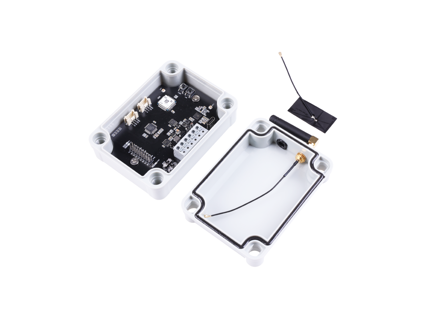
Part List
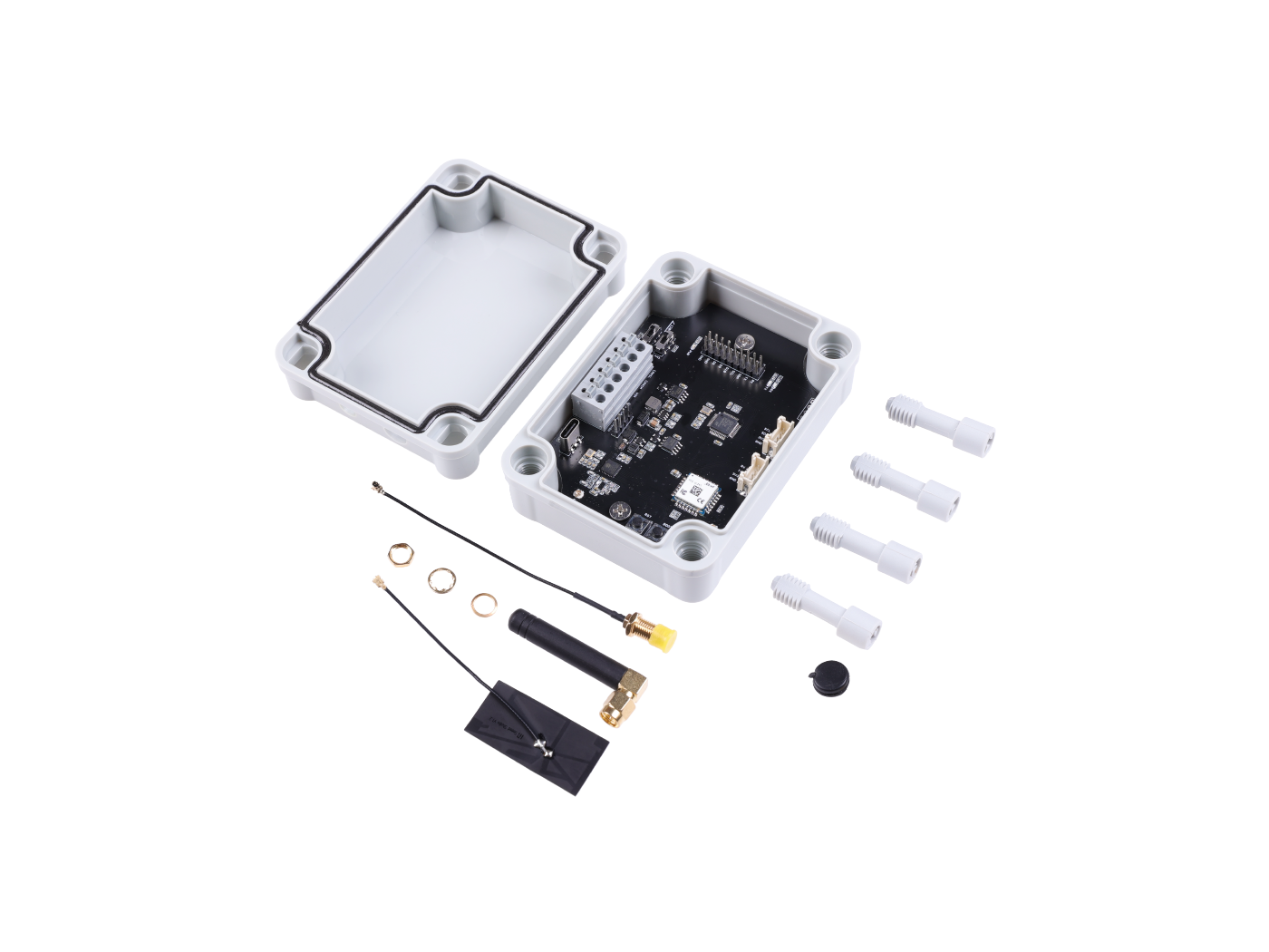
- Wio ESP32 CAN Dev Board x 1
- 2.4G Wi-Fi Antenna for ESP32
- 915Mhz Antenna for Wio E5 module
- Waterproof rubber stopper
- Antenna Adapter for the 915Mhz antenna
Arduino IDE Setup
The board support Arduino IDE, please folow below steps to use Arduino IDE to program the board.
Please download the latest Arduino IDE.
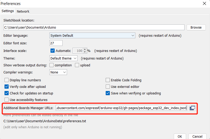
Launch the Arduino IDE and navigate to File > Preferences and fill Additional Boards Manager URLs with below,
https://raw.githubusercontent.com/espressif/arduino-esp32/gh-pages/package_esp32_dev_index.json
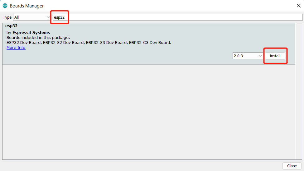
Navigate to Tools > Board > Boards Manager, type the keyword "esp32" in the search box, select the latest version of esp32, and install it.
After the boars intalled well, please select XIAO_ESP32C2 when compile your code.
Usage for LoRa

The kit use Wio-E5 Wireless Module as the LoRa controller, we already have a detailed tutorial for it.
Please refer to Wiki for Wio-E5 Wireless Module.
Usage for CAN FD
Download the install the library
Get the Arduino library
Open the Arduino IDE, navigate to Sketch > Include Library > Add .ZIP Library to install the Library.
Hardware Connection
Please conect CAN0H to CAN1H, CAN0L to CAN1L.
Open the code and upload it to the board
Open the Arduino IDE, here we open the CAN20_SendRecv example. This example can continuously send data to the CAN Bus.
// CANBED DUAL TEST EXAMPLE
// CAN 0 Send, CAN 1 Recv

#include <Wire.h>
#include <stdio.h>
#include "canbed_dual.h"

CANBedDual CAN0(0);
CANBedDual CAN1(1);

void setup()
{
    Serial.begin(115200);
    Wire.begin();
    CAN0.init(500000);          // CAN0 baudrate: 500kb/s
    CAN1.init(500000);          // CAN1 baudrate: 500kb/s
}

void loop()
{
    sendData();

    unsigned long id = 0;
    int ext = 0;
    int rtr = 0;
    int fd  = 0;
    int len = 0;

    unsigned char dtaGet[100];

    if(CAN1.read(&id, &ext, &rtr, &fd, &len, dtaGet))
    {
        Serial.println("CAN1 GET DATA");
        Serial.print("id = ");
        Serial.println(id);
        Serial.print("ext = ");
        Serial.println(ext);
        Serial.print("rtr = ");
        Serial.println(rtr);
        Serial.print("fd = ");
        Serial.println(fd);
        Serial.print("len = ");
        Serial.println(len);

        for(int i=0; i<len; i++)
        {
            Serial.print(dtaGet[i]);
            Serial.print("\t");
        }
        Serial.println();
    }
}

void sendData()
{
    static unsigned long timer_s = millis();
    if(millis()-timer_s < 100)return;
    timer_s = millis();

    static unsigned int cnt = 0;
    cnt++;
    if(cnt > 99)cnt = 0;
    unsigned char str[8];
    for(int i=0; i<8; i++)str[i] = cnt;
    CAN0.send(0x01, 0, 0, 0, 8, str);
}

// ENDIF
After the uploading is done, open the Serial monitor, you will see data printed to the monitor.