Motor Driver Card
Introduction
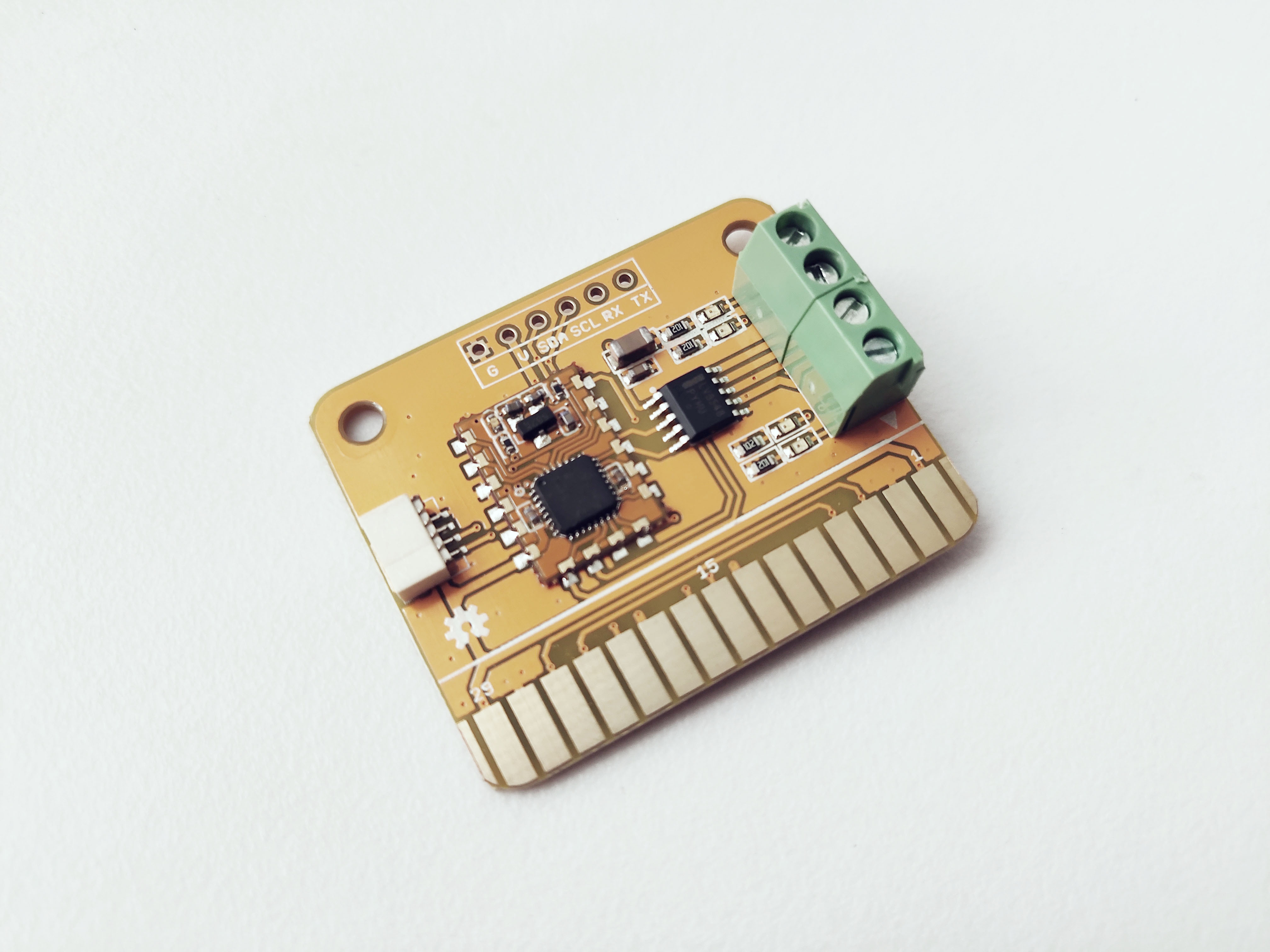
The Motor Driver Card features LV8548MC, which is a 2-channel motor driver IC. It can drive two DC motors or one DC motor using the parallel connection, or it can drive a stepper motor in full-step and half-step.
Specifications
- Features LV8548 motor driver
- Supports two wire I2C bus interface
- One 4 pin SH1.0 connectors -allows you to connect MCUs or cards which support I2C communication protocol with dupont cables.
- 30 gold fingers
- ATmega 168PA microprocessor - runs card firmware.
- LED indicator – flashes when Carduino read/write data from/to the card through I2C.
- 4-pin terminal block connector
- Voltage: 5V
- Built-in brake function
- Motor speed and direction control
How to Connect Motors
- Take two DC motors.
- Connect one motor to the terminal block has pin 1 and 2.
- Connect other motor to the terminal block ha spin 3 and 4.
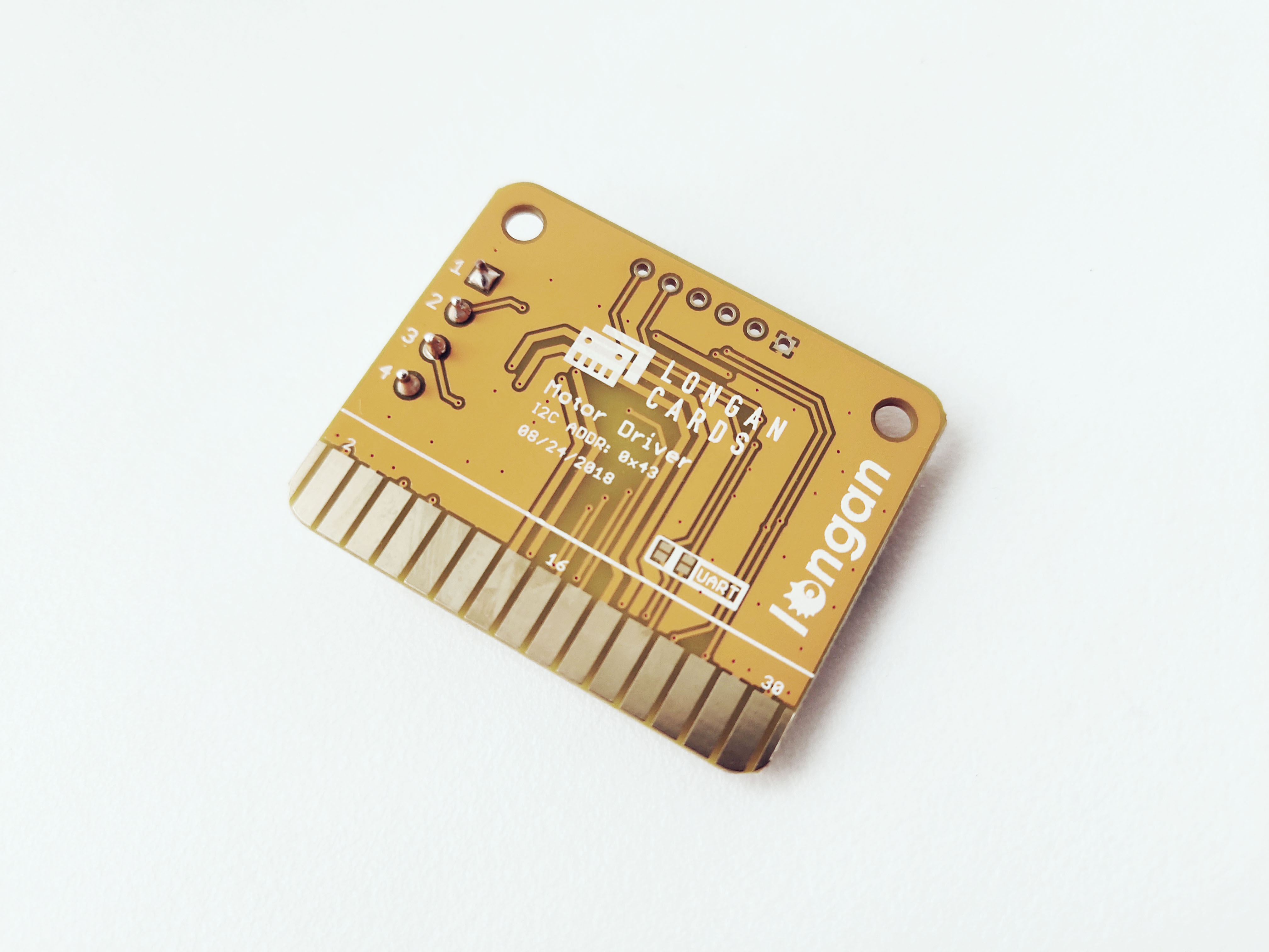
I2C Address
The default I2C address is printed on the back side of the card which is 0x43. However, you can change it to a different address with the card firmware (Read our wiki for how to change the default I2C address of a card.).
Pins
The edge connector (gold fingers) has total of 30 contacts (each side has 15 contacts).
On the front side of the Motor Driver Card, a white arrow is printed near the edge connector indicates the pin #1. You can find some pin numbers printed on the edge connector itself (1, 15, and 29). You can count the pin numbers starting with 1 and count by twos from right to left would be 1, 3, 7, 9, 11, 15, 17, 19, 21, 23, 27, and 29. Notice that all the counts are odd numbers.
On the back side of the Motor Driver Card, you also can find some pin numbers printed on the edge connector itself (2, 16, and 30). You can count the pin numbers starting with 2 and count by twos from left to right would be 2, 4, 6, 8, 10, 12, 14, 16, 18, 20, 22, 24, 26, 28 and 30. Notice that all the counts are even numbers.
Among the 30 pins, following pins can be used for I2C communication.
- SDA: Digital I/O, I2C bus serial bidirectional data line (Front: pin #5, #25 / Back: pin #6, #26)
- SCL: Digital Input, I2C bus serial clock input (Front: pin #7, #23 / Back: pin #8, #24)
Also, following pins connect with the common power bus of the board.
- VCC: Power supply (Front: pin #1, #29 / Back: pin #2, #30)
- GND: To be connected to the system ground (Front: pin #3, #27 / Back: pin #4, #28)
How to Use
The Motor Driver Card can be plugged into an edge connector slot of one of the following Longan boards.
- Game board
- Car board
- Sensor board
- Extension board
- PI Hap
However, it is best suited for the Longan Car Board.
When you plug, the white arrow head printed on the card should be pointing toward the white arrow head printed near the edge connector slot of the board. Once plugged, it can communicate with the Carduino through the I2C bus line of the board. It will also connect to the common power bus of the board.
Example 1
Coming soon.