CANBED M4
Introduction
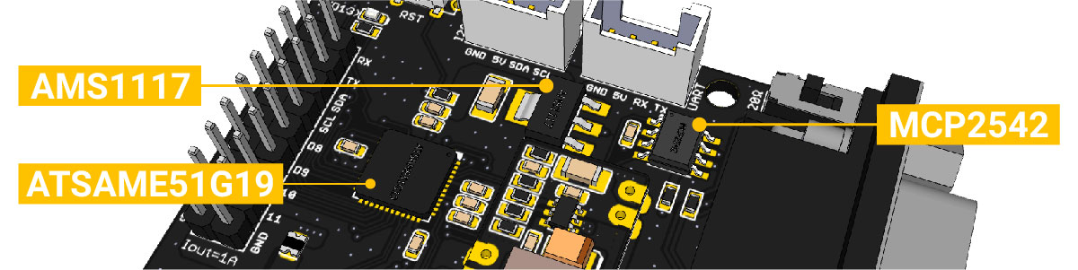
CAN Bus is a common industrial bus because of its long travel distance, medium communication speed and high reliability. It is commonly found on modern machine tools, such as an automotive diagnostic bus. This CANBed M4 is the latest board of the CANBed family, with the ATSAME51G19A mcu and MCP2542FD CAN transceiver to achieve the CAN-FD capability.
Click to get a DB9 to OBD-II cable.
CANBed Family
Currently we have 6 CANBeds, you can choose the right one according to your needs.
| VRESION | CANBed V1 | CANBed FD | CANBed M0 | CANBed M4 | CANBed RP2040 | CANBed Dual |
|---|---|---|---|---|---|---|
| MCU | Atmega32U4 | Atmega32U4 | ATSAMD21G18 | ATSAME51G19A | RP2040 | RP2040 |
| CORE | AVR 8 bit | AVR 8 bit | ARM Cortex M0+ 32bit | ARM Cortex M4 32bit | Dual ARM Cortex-M0+ | Dual ARM Cortex-M0+ |
| PROTOCOL | CAN2.0 | CANFD & CAN2.0 | CAN2.0 | CANFD & CAN2.0 | CAN2.0 | CANFD & CAN2.0 |
| CLOCK | 16MHz | 16MHz | 48MHz | 133MHz | 133MHz | 133MHz |
| FLASH | 32KB | 32KB | 256KB | 2MKB | 2MKB | 2MKB |
| RAM | 2.5KB | 2.5KB | 32KB | 192KB | 264KB | 264KB |
| PRICE | $24.9 | $29.9 | EoL | $49.9 | $15.9 | $24.9 |
| LINK | GET ONE | GET ONE | GET ONE | GET ONE | GET ONE | GET ONE |
Note
The above price may not be the latest price, please refer to the price on the product page.
CAN BUS PRODUCTS LIST OF LONGAN LABS

We have made a lot of can bus products, you can get more information through the following list, so as to choose a product suitable for you.
| PRODUCT NAME | LINK | PRICE | MCU | CHIP | PROTOCOL |
|---|---|---|---|---|---|
| Serial CAN Bus Module | LINK | $19.9 | ATMEGA168PA | MCP2515 | CAN2.0 |
| I2C CAN Bus Module | LINK | $19.9 | ATMEGA168PA | MCP2515 | CAN2.0 |
| OBD-II Serial CAN Bus Dev Kit | LINK | $20.9 | ATMEGA168PA | MCP2515 | CAN2.0 |
| OBD-II CAN Bus GPS Dev Kit | LINK | $29.9 | ATMEGA32U4 | MCP2515 | CAN2.0 |
| OBD-II CAN Bus Basic Dev Kit | LINK | $24.9 | ATMEGA32U4 | MCP2515 | CAN2.0 |
| CAN-FD Shield | LINK | $19.9 | NO MCU | MCP2517FD | CAN-FD |
| CAN Bus Shield | LINK | $9.9 | NO MCU | MCP2515 | CAN2.0 |
| CANBed | LINK | $24.9 | ATMEGA32U4 | MCP2515 | CAN2.0 |
| CANBed-FD | LINK | $29.9 | ATMEGA32U4 | MCP2517FD | CAN-FD |
| CANBed M4 | LINK | $49.9 | ATSAME51 | - | CAN-FD |
| OBD-II RF Dev Kit | LINK | $19.9 | ATmega168PA | MCP2515 | CAN2.0 |
Note
The above price may not be the latest price, please refer to the price on the product page.
Features
- CAN-FD and CAN2.0
- ATSAME51G19A 32bit Cortex M4 core
- 512 KB flash, 192KB RAM
- Industrial standard 9 pin sub-D connector or 4PIN Terminal Connector
- OBD-II and CAN standard pinout selectable at sub-D connector
- 2x4Pin Connector compatable with Grove system
- Size: 56x41mm
Specifications
- MCU: ATSAME51 32bit Cortex M4 core
- Clock speed: 120MHz
- Flash memory: 512KB
- RAM: 192KB
- EEPROM: No EEPROM
- Input voltage: 7~28V
- Output Current @ 5V: 1A
- Input interface: Sub-D as well as Terminal
CAN Baudrate Support
For CAN-FD frame, below baudrate are supported,
- CAN_250K_500K
- CAN_250K_1M
- CAN_250K_1M5
- CAN_250K_2M
- CAN_500K_1M
- CAN_500K_2M
- CAN_500K_4M
- CAN_1000K_4M
For CAN standard frame, below baudrates are supported.
- CAN_4K096BPS
- CAN_5KBPS
- CAN_10KBPS
- CAN_20KBPS
- CAN_31K25BPS
- CAN_33K3BPS
- CAN_40KBPS
- CAN_50KBPS
- CAN_80KBPS
- CAN_100KBPS
- CAN_125KBPS
- CAN_200KBPS
- CAN_250KBPS
- CAN_500KBPS
- CAN_1000KBPS
Hardware Overview
Part List
Note
In consideration of convenient transportation and cost reduction, there are some materials that you need to solder by hand. If you don't have soldering iron tools, you can also ask our engineers to do it for you. After you place an order, email info@longan-labs.
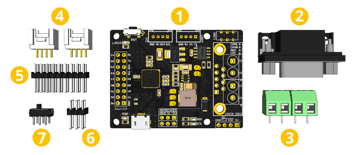
- CANBed M4 PCBA
- sub-D connector
- 4PIN Terminal
- 4PIN 2.0 Connector x 2
- 9x2 2.54 Header x 1
- 3x3 2.54 Header x 1
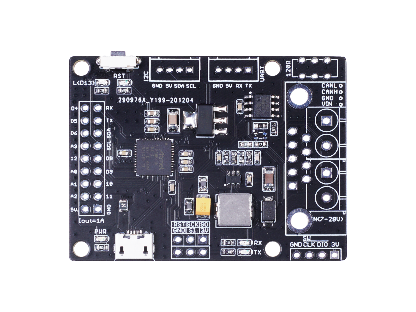
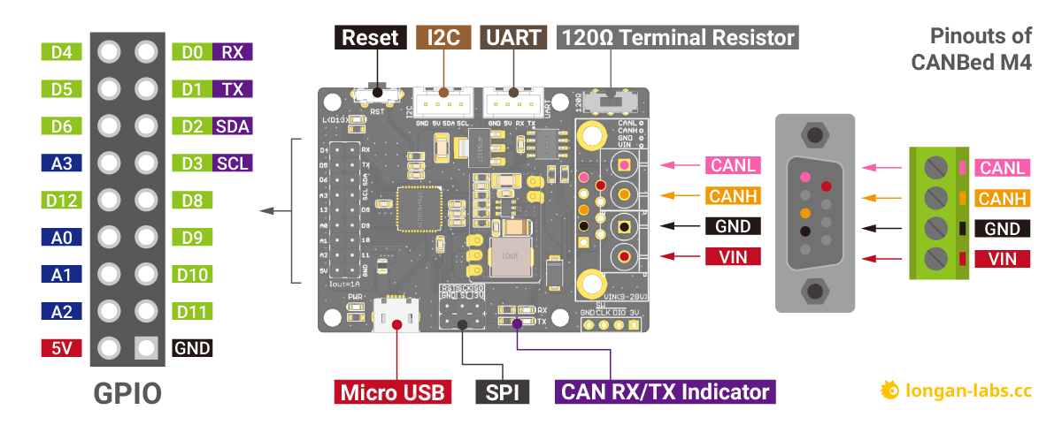
Pin out
1.9x2 IO Pin OUT:
The IO of Atsame51 is list out here.
2.ATSAME51G19A:
Cortex M4 core controller
2.Reset Button:
Reset the on-board Atmega chip.
3.Micro USB connector for programming
4. SPI Interface
5.CAN RX/TX Indicator
6.sub-D connector or Terminal for CAN Bus
D-Sub CANbus PinOut
| pin# | Signal names | Signal Description |
|---|---|---|
| 1 | Reserved | Upgrade Path |
| 2 | CAN_L | Dominant Low |
| 3 | CAN_GND | Ground |
| 4 | Reserved | Upgrade Path |
| 5 | CAN_SHLD | Shiled, Optional |
| 6 | GND | Ground,Optional |
| 7 | CAN_H | Dominant High |
| 8 | Reserved | Upgrade Path |
| 9 | CAN_V+ | Power, Optional |
7.Switch for the 120Ω terminal resistor for CAN Bus

If you use this board on the end of the CAN bus, please put this switch to 120Ω. For more detail about the CAN bus protocol, please refer to the NI CAN Physical Layer and Termination Guide
8.Grove connector for UART
9.Grove connector for I2C
DB9 connector
The DB9 interface of CAN Bus has two different protocols, OBD and CAN Open. Their definition is as follows,
| pin# | OBD(default) | CAN OPEN |
|---|---|---|
| 1 | GND | N.C |
| 2 | GND | CAN_L |
| 3 | CANH | GND |
| 4 | N.C | N.C |
| 5 | CANL | GND |
| 6 | N.C | N.C |
| 7 | N.C | CAN_H |
| 8 | N.C | N.C |
| 9 | CAN_V+ | CAN_V+ |
If you want to use the OBD protocol, you don't need to make any changes to the hardware.
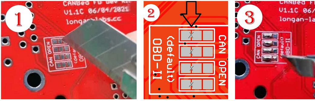
If you need to use the CAN Open protocol, first we look at the back side of the PCB board, you can see the Pads below,
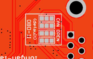
These pads are connected to the OBD side by default. We have to prepare a knife to disconnect the OBD side, and then use an electric soldering iron to solder the CAN Open side of the pads.
Getting Started with Arduino IDE
Arduino IDE Setup
First download the Arduino IDE from https://www.arduino.cc/en/Main/Software. Arduino IDE can be installed and run on Windows, Linux, and Mac OS X operating systems. Download the installer or zip file (Windows only) and install (if you have the zip file, extract it to your Windows computer’s hard drive) it on your operating system.
Once finished, start the Arduino IDE.
Copy and paste the link below into the Additional Boards Manager URLs option in the Arduino IDE preferences (File > Preferences).
https://raw.githubusercontent.com/Longan-Labs/LONGAN-SAME-TOOLS/master/package_longan_samd_index.json
Enter longan to install the latest Longan SAME board
Example code
Open Arduino IDE, Click File > Examples > SAME51 CAN Library, you will get many examples for CANBed M4.
There're many examples for the library, which is consist of,
- CAN_20_Send - How to send a frame to CAN Bus 2.0
- CAN_20_Recv - How to recv a frame from CAN Bus 2.0
- CAN_FD_Send - How to send a frame to CAN FD
- CAN_FD_Recv - How to recv a frame from CAN FD
Rescue the bricked board
Sometimes due to some strange reasons, your board can no longer burn any program, and the USB cannot be recognized. At this time, you can save your board by the following methods
First of all you need a J-Link tool, if you don't have it, you can get one from Longan Labs.
Please folow below steps.
-
Get a J-Link tool
-
Download the J-Flash software
-
Install the J-Link Software, then you will get a J-Flash tool.
-
Download the bootloader file.
-
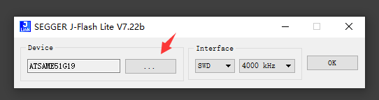
Open J-Flash software, Click to select the MCU.
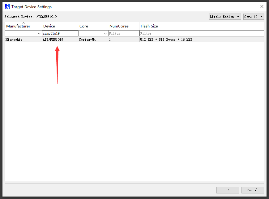
6.Find SAME51G19A
7.Point to the bootloader file
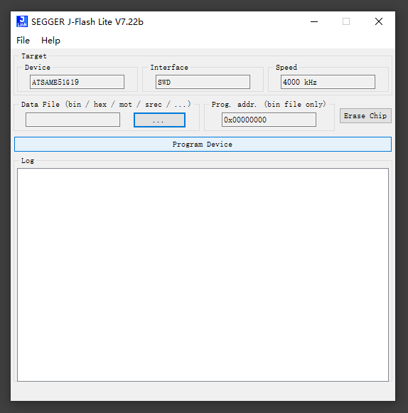
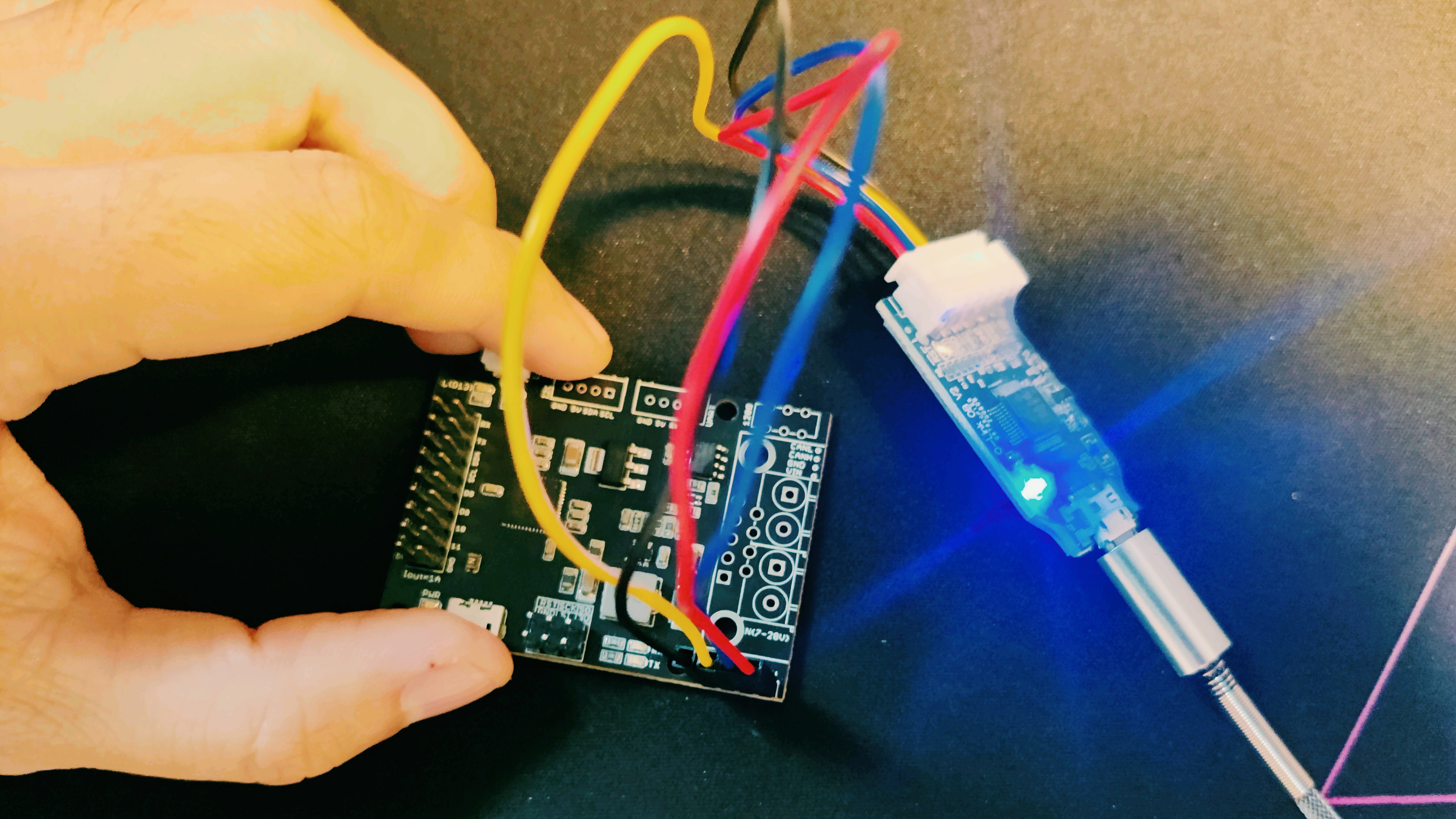
8.Connect SWD interface to the board.
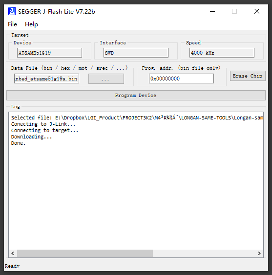
9.Click on Program Device, if everything is ok, you saved the board now.
FAQ
The RX/TX led light up and never turn off
- Check if the baudrate of CAN Bus is setting correct
- Try turning on/off the switch for the terminal resistor
- Cehck if CANH and CANL is connected correct
How to find the tech support
Please contact support@longan-labs.cc for technical support. Our technical support engineer will usually reply you within 24 hours on working days. In order to get faster support, we hope that when you send us an email, you need to include at least the following content,
- When and how to buy the product
- Product version information
- Take a high-definition picture of the product you use, including the connection
- Describe in detail the problem you encountered and what kind of help you would like to get