CANBed with CASE Atmega32U4 Version
Introduction
A few years ago, we released a popular CAN Bus development board called CANBed. Many users have completed their own projects using this development board and shared their projects with us. We noticed that some users needed to make their own enclosure, either using 3D printing or a cardboard box.
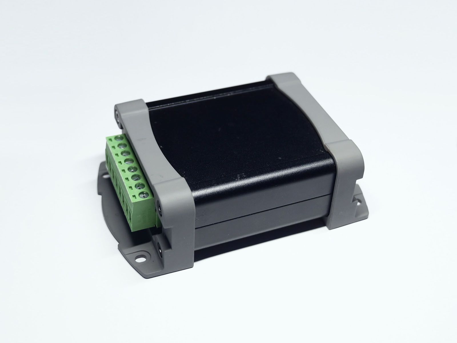
Today, we are excited to announce the release of the CANBed with an aluminum housing. Like the original CANBed, this version features an Atmega32U4 microcontroller, MCP2515 and MCP2551 chips, and supports USB power supply or 7-28V DC input.
In the future, we will continue to release additional versions, including the RP2040 version and CAN-FD series products.
Possible Applications
This CAN Bus dev kit can be used for the following purposes:
- Learning about CAN Bus communication
- Building product prototypes, and integrating the completed prototype into a final product with assistance from the manufacturer
- Reading data from a car's systems
- Incorporating into a final product as a complete MCU and CAN Bus solution, requiring only external hardware design.
CANBed Family
There are currently six different versions of CANBed available, each with different features and capabilities. You can choose the one that best suits your needs from the following options:
| VRESION | CANBed V1 | CANBed FD | CANBed M0 | CANBed M4 | CANBed RP2040 | CANBed Dual |
|---|---|---|---|---|---|---|
| MCU | Atmega32U4 | Atmega32U4 | ATSAMD21G18 | ATSAME51G19A | RP2040 | RP2040 |
| CORE | AVR 8 bit | AVR 8 bit | ARM Cortex M0+ 32bit | ARM Cortex M4 32bit | Dual ARM Cortex-M0+ | Dual ARM Cortex-M0+ |
| PROTOCOL | CAN2.0 | CANFD & CAN2.0 | CAN2.0 | CANFD & CAN2.0 | CAN2.0 | CANFD & CAN2.0 |
| CLOCK | 16MHz | 16MHz | 48MHz | 133MHz | 133MHz | 133MHz |
| FLASH | 32KB | 32KB | 256KB | 2MKB | 2MKB | 2MKB |
| RAM | 2.5KB | 2.5KB | 32KB | 192KB | 264KB | 264KB |
| PRICE | $24.9 | $29.9 | EoL | $49.9 | $15.9 | $24.9 |
| LINK | GET ONE | GET ONE | GET ONE | GET ONE | GET ONE | GET ONE |
Note
The prices listed above may not be the most recent and should be checked on the product page for accuracy.
CAN BUS PRODUCTS LIST OF LONGAN LABS

We offer a range of CAN Bus products that may be suitable for your needs. You can find more information about these products in the list below and choose the one that best meets your requirements.
| PRODUCT NAME | LINK | PRICE | MCU | CHIP | PROTOCOL |
|---|---|---|---|---|---|
| Serial CAN Bus Module | LINK | $19.9 | ATMEGA168PA | MCP2515 | CAN2.0 |
| I2C CAN Bus Module | LINK | $19.9 | ATMEGA168PA | MCP2515 | CAN2.0 |
| OBD-II Serial CAN Bus Dev Kit | LINK | $20.9 | ATMEGA168PA | MCP2515 | CAN2.0 |
| OBD-II CAN Bus GPS Dev Kit | LINK | $29.9 | ATMEGA32U4 | MCP2515 | CAN2.0 |
| OBD-II CAN Bus Basic Dev Kit | LINK | $24.9 | ATMEGA32U4 | MCP2515 | CAN2.0 |
| CAN-FD Shield | LINK | $19.9 | NO MCU | MCP2517FD | CAN-FD |
| CAN Bus Shield | LINK | $9.9 | NO MCU | MCP2515 | CAN2.0 |
| CANBed | LINK | $24.9 | ATMEGA32U4 | MCP2515 | CAN2.0 |
| CANBed-FD | LINK | $29.9 | ATMEGA32U4 | MCP2517FD | CAN-FD |
| CANBed M4 | LINK | $49.9 | ATSAME51 | - | CAN-FD |
| OBD-II RF Dev Kit | LINK | $19.9 | ATmega168PA | MCP2515 | CAN2.0 |
Note
The prices listed above may not be the most recent and should be checked on the product page for accuracy.
Features
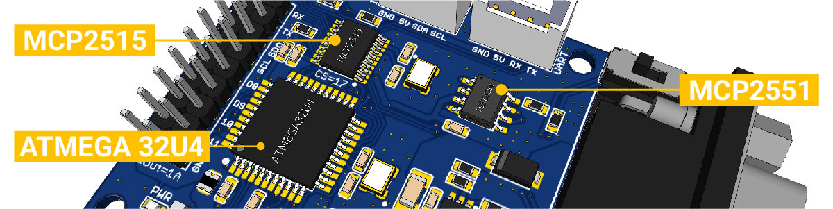
- Atmega32U4 microcontroller with Arduino Leonardo bootloader on the board
- MCP2515 CAN Bus controller and MCP2551 CAN Bus transceiver
- OBD-II and CAN standard pinout options available at the Sub-D connector
- Compatibility with the Arduino IDE
Specifications
| Parameter | Value |
|---|---|
| MCU | Atmega32U4 (with Arduino Leonardo bootloader) |
| Clock Speed | 16MHz |
| Flash Memory | 32KB |
| SRAM | 2.5KB |
| EERROM | 1KB |
| Operate Voltage | 9-28V |
| Output Current @ 5V | 1A |
Hardware Overview
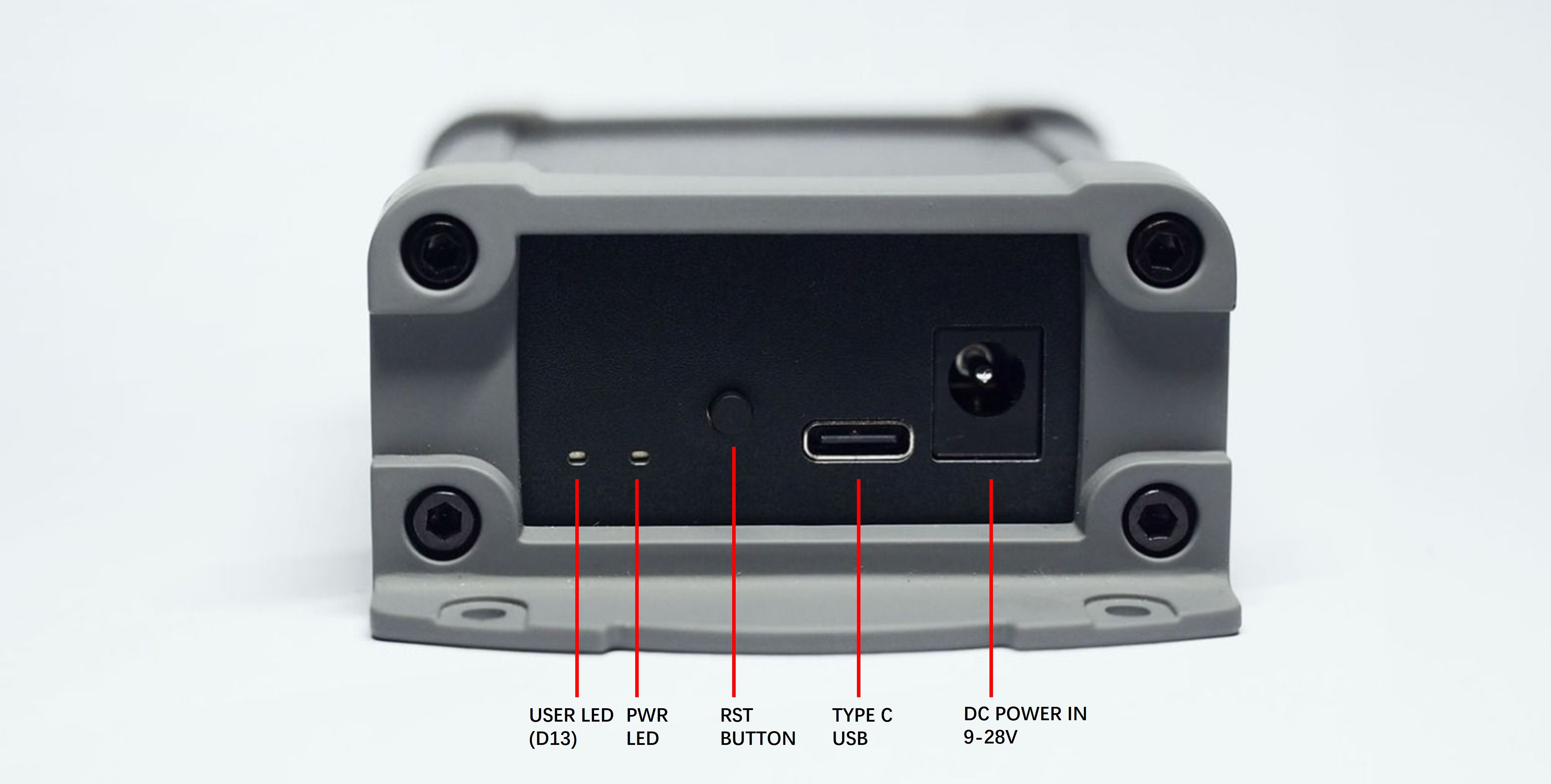
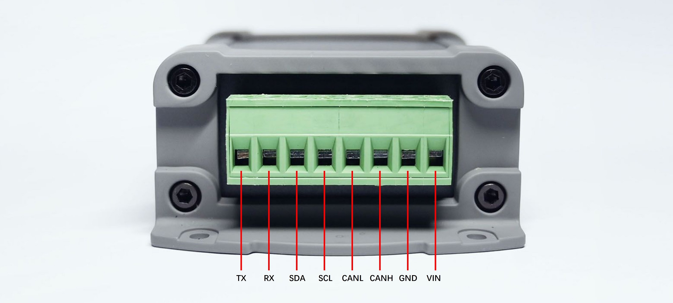
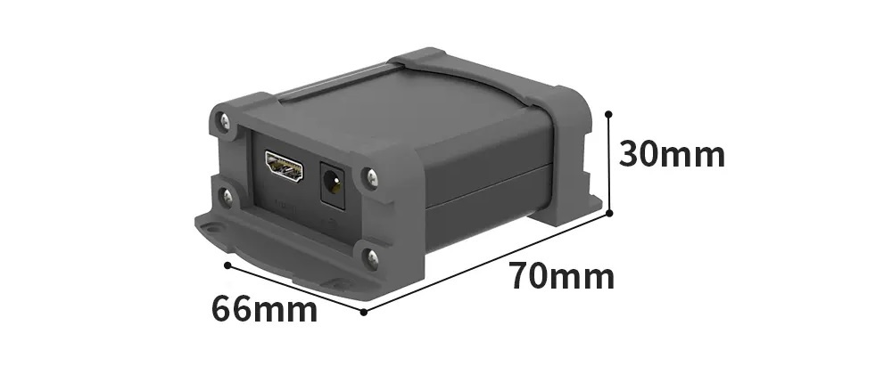
PIN OUT
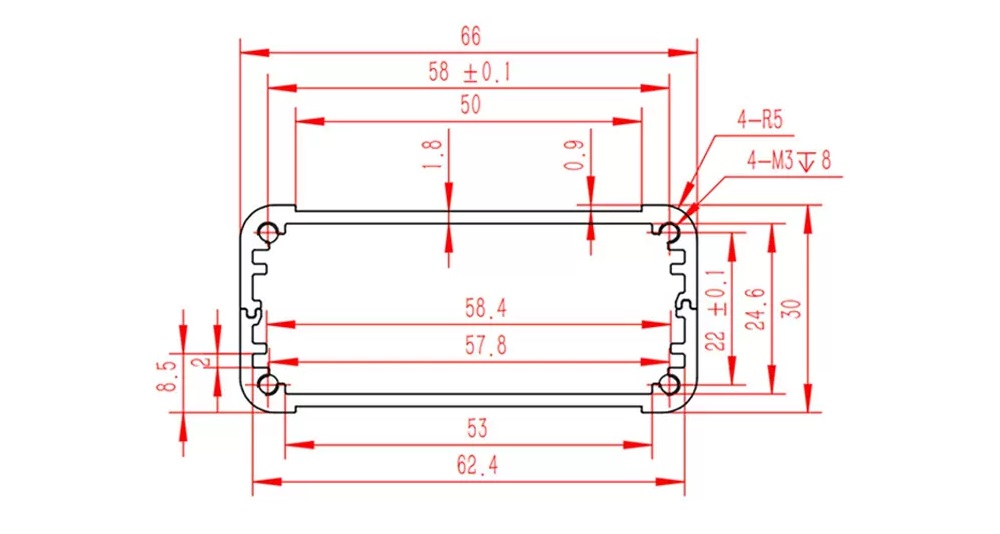
SIZE
Getting Started
In this section, we will demonstrate how to get started with CANBed using the Arduino IDE. You will need a micro USB cable to connect the CANBed development board to your computer.
IDE and Driver
There is an Arduino Leonardo bootloader on the board.
To get the latest Arduino IDE, click here.
The Arduino Leonardo driver can be found in the folder: Arduino/drivers.
Download the install the library
Click to get the Arduino Library for CANBed Dev board.
In the Arduino IDE, navigate to Sketch > Include Library > Add .ZIP Library to install the Library.
Open the code and upload it to the board
Open the Arduino IDE, here we open the send example. This example can continuously send data to the CAN Bus.
#include <mcp_can.h>
#include <SPI.h>

const int SPI_CS_PIN = 17;              // CANBed
// const int SPI_CS_PIN = 3;            // CANBed M0
// const int SPI_CS_PIN = 9;            // CAN Bus Shield

MCP_CAN CAN(SPI_CS_PIN);                                    // Set CS pin

void setup()
{
    Serial.begin(115200);
    while(!Serial);

    // below code need for OBD-II GPS Dev Kit
    // pinMode(A3, OUTPUT);
    // digitalWrite(A3, HIGH);

    while (CAN_OK != CAN.begin(CAN_500KBPS))    // init can bus : baudrate = 500k
    {
        Serial.println("CAN BUS FAIL!");
        delay(100);
    }
    Serial.println("CAN BUS OK!");
}

unsigned char stmp[8] = {0, 1, 2, 3, 4, 5, 6, 7};
void loop()
{
    CAN.sendMsgBuf(0x00, 0, 8, stmp);
    delay(100);                       // send data per 100ms
}

// END FILE
You need to select Arduino Leonardo on the Arduino IDE boards and select the correct COM port. Then you can upload the program to the CANBed Dev board by pressing the Upolading button on Arduino IDE.
Get data from a Vehicle
We can use CANBed to get data from a vehicle, we take the vehicle speed for an example here.
You can use our products to read data from cars. Here we provide a simple example by which you can read the speed and revs from a car. This is the OBD-based PIDs protocol. Regarding the deeper technology of OBD, we can't provide support at present. You may need to have some understanding of the car's protocol. After all, we are more of a hardware supplier.
Using CANBed, you can retrieve data from a vehicle. For example, you can read the speed and revs of a car using our products and the OBD-based PIDs protocol. While we can provide hardware support, we are unable to offer support for the deeper technology of OBD at this time. It is recommended to have some understanding of the car's protocol before attempting to retrieve data.
The interface of OBD is as follows,
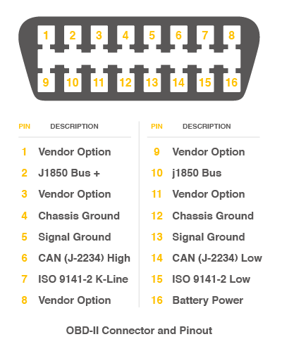
There're 4 pins we need to connect.
| OBD Pin | CANBed PIN |
|---|---|
| 5. Signal Ground | GND |
| 6. CAN(J-2234) High | CANH |
| 14. CAN(J-2234) Low | CANL |
| 16. Battery Power | VIN |
You can also use our OBD-II to DB9 Cable, which is very convenient to connect to OBD.
To retrieve the speed from a car using the development board, upload the following code and open the serial monitor.
#include <SPI.h>
#include "mcp_can.h"

/* Please modify SPI_CS_PIN to adapt to different baords.

   CANBed V1        - 17
   CANBed M0        - 3
   CAN Bus Shield   - 9
   CANBed 2040      - 9
   CANBed Dual      - 9
   OBD-2G Dev Kit   - 9
   Hud Dev Kit      - 9
*/

#define SPI_CS_PIN  17

MCP_CAN CAN(SPI_CS_PIN);                                    // Set CS pin

#define PID_ENGIN_PRM       0x0C
#define PID_VEHICLE_SPEED   0x0D
#define PID_COOLANT_TEMP    0x05

#define CAN_ID_PID          0x7DF

void set_mask_filt()
{
    // set mask, set both the mask to 0x3ff

    CAN.init_Mask(0, 0, 0x7FC);
    CAN.init_Mask(1, 0, 0x7FC);

    // set filter, we can receive id from 0x04 ~ 0x09

    CAN.init_Filt(0, 0, 0x7E8);
    CAN.init_Filt(1, 0, 0x7E8);

    CAN.init_Filt(2, 0, 0x7E8);
    CAN.init_Filt(3, 0, 0x7E8);
    CAN.init_Filt(4, 0, 0x7E8);
    CAN.init_Filt(5, 0, 0x7E8);
}

void sendPid(unsigned char __pid) {
    unsigned char tmp[8] = {0x02, 0x01, __pid, 0, 0, 0, 0, 0};
    CAN.sendMsgBuf(CAN_ID_PID, 0, 8, tmp);
}

bool getSpeed(int *s)
{
    sendPid(PID_VEHICLE_SPEED);
    unsigned long __timeout = millis();

    while(millis()-__timeout < 1000)      // 1s time out
    {
        unsigned char len = 0;
        unsigned char buf[8];

        if (CAN_MSGAVAIL == CAN.checkReceive()) {                // check if get data
            CAN.readMsgBuf(&len, buf);    // read data,  len: data length, buf: data buf

            if(buf[1] == 0x41)
            {
                *s = buf[3];
                return 1;
            }
        }
    }

    return 0;
}

void setup() {
    Serial.begin(115200);
    while(!Serial);

    // below code need for OBD-II GPS Dev Kit
    // pinMode(A3, OUTPUT);
    // digitalWrite(A3, HIGH);

    while (CAN_OK != CAN.begin(CAN_500KBPS)) {             // init can bus : baudrate = 500k
        Serial.println("CAN init fail, retry...");
        delay(100);
    }
    Serial.println("CAN init ok!");
    set_mask_filt();
}

void loop() {

    int __speed = 0;
    int ret = getSpeed(&__speed);
    if(ret)
    {
        Serial.print("Vehicle Speed: ");
        Serial.print(__speed);
        Serial.println(" kmh");
    }
    delay(500);
}

// END FILE
To retrieve other data using PIDs, you can refer to the example provided and to this link.
Arduino Code
We provide an Arduino library for CANBed.
Note
Please change the SPI_CS_PIN to 17 for CANBed
The library includes several examples, including:
- OBDII-PIDs - retrieve data from the OBD-II interface
- send - send a frame to the CAN bus
- recv - receive a frame from the CAN bus
- set_mask_filter_recv - receive a frame from the CAN bus with mask and filter settings
APIs
1. Set the Baud rate
This function is used to initialize the baud rate of the CAN Bus system.
The available baud rates are listed as follows:
#define CAN_5KBPS    1
#define CAN_10KBPS   2
#define CAN_20KBPS   3
#define CAN_25KBPS   4
#define CAN_31K25BPS 5
#define CAN_33KBPS   6
#define CAN_40KBPS   7
#define CAN_50KBPS   8
#define CAN_80KBPS   9
#define CAN_83K3BPS  10
#define CAN_95KBPS   11
#define CAN_100KBPS  12
#define CAN_125KBPS  13
#define CAN_200KBPS  14
#define CAN_250KBPS  15
#define CAN_500KBPS  16
#define CAN_666kbps  17
#define CAN_1000KBPS 18
2. Set Receive Mask and Filter
The controller chip has 2 receive mask registers and 5 filter registers that can be used to ensure that data is received from the targeted device. These registers are particularly useful in large networks with many nodes. We have provided two functions that allow you to utilize these mask and filter registers.
Mask:
init_Mask(unsigned char num, unsigned char ext, unsigned char ulData);
Filter:
init_Filt(unsigned char num, unsigned char ext, unsigned char ulData);
- num represents which register to use. You can fill 0 or 1 for mask and 0 to 5 for filter.
- ext represents the status of the frame. 0 means it's a mask or filter for a standard frame. 1 means it's for a extended frame.
- ulData represents the content of the mask of filter.
3. Check Receive
The MCP2515 controller chip has the ability to operate in either a polled mode or an interrupt mode. In polled mode, the software regularly checks for a received frame. In interrupt mode, additional pins can be used to signal that a frame has been received or transmit has completed. This allows for more efficient use of resources as the processor does not need to constantly check for incoming data.
This function is used to check if there are any received frames waiting in the receive buffer. If there are, the function will return true, otherwise it will return false. You can use this function in a loop to continuously check for received frames.
INT8U MCP_CAN::checkReceive(void);
4. Get CAN ID
You can use the following function to get the length of the data received from the "send" node.
INT32U MCP_CAN::getCanId(void)
5. Send a frame
CAN.sendMsgBuf(INT8U id, INT8U ext, INT8U len, data_buf);
This function is used to send data onto the CAN Bus. The parameters are as follows:
- id - The ID of can frame.
- ext - A boolean value representing the status of the frame. '0' means standard frame. '1' means extended frame.
- len - The length of the frame.
- data_buf - The content of the message.
For example, In the 'send' example, we have:
unsigned char stmp[8] = {0, 1, 2, 3, 4, 5, 6, 7};
CAN.sendMsgBuf(0x00, 0, 8, stmp); //send out the message 'stmp' to the bus and tell other devices this is a standard frame from 0x00.
6. Receive a frame
The following function is used to receive data on the 'receive' node:
CAN.readMsgBuf(unsigned char len, unsigned char buf);
In conditions that masks and filters have been set. This function can only get frames that meet the requirements of masks and filters.
- len represents the data length.
- buf is where you store the data.
FAQ
I can't upload code to CANBed
- Make sure that the correct COM port and board type are selected in the Arduino IDE.
- Try unplugging and replugging the USB cable to reset the connection.
- Try restarting the Arduino IDE.
- Make sure that you are using the correct driver for the board. If you are using a Windows computer, you may need to install the driver manually. The driver can usually be found in the Arduino installation folder under "drivers".
- If you are still unable to upload code to the board, there may be a hardware issue. Try using a different micro USB cable or testing the board on a different computer. If the issue persists, please contact support@longan-labs.cc for further assistance.
The RX/TX led light up and never turn off
- Check if the baud rate of the CAN Bus is set correctly. The baud rate should match the baud rate of the other devices on the CAN Bus.
- Try turning the switch for the 120Ω terminal resistor on and off.
- Check that the connections for CANH and CANL are correct. They should be connected to the corresponding lines on the other devices on the CAN Bus.
- Make sure that the frame being sent or received is properly formatted and does not have any errors.
How to find technical support
If you are experiencing any issues with the CANBed board or have any technical questions, please contact support@longan-labs.cc for assistance. In your email, please include as much detail as possible about the problem you are experiencing, including when and how you purchased the product, the version of the product you are using, and any relevant pictures or error messages. Our technical support team will do their best to help you resolve any issues and get your project up and running as quickly as possible.