Carduino 328
Introduction
Carduino 328 is the new development board belongs to the Longan Cards Family. As its name implies it is small as ⅓ of a credit card, thin, and light weight.
Carduino 328 is a microcontroller board based on the ATmega328P. You can use it with any Longan board by plugging it into one of the edge connector slots. Carduino 328 supports all the Longan cards.
Carduino 328 is pluggable, which means you can plug it to one of the following boards.
- Extension board
- Sensor display board
- Game board
- Car board
- Pi Hap
There is a wide array of cards support with the Carduino 328. All cards are pluggable and share the same board to communicate with the Carduino 328. Carduino 328 allow you to quickly build prototypes and develop applications.
At the Carduino’s heart is an ATmega328P microprocessor and powered with the Arduino UNO bootloader allows you to program it using the Arduino IDE. We have written some exciting Arduino libraries that lets you to quickly develop applications.
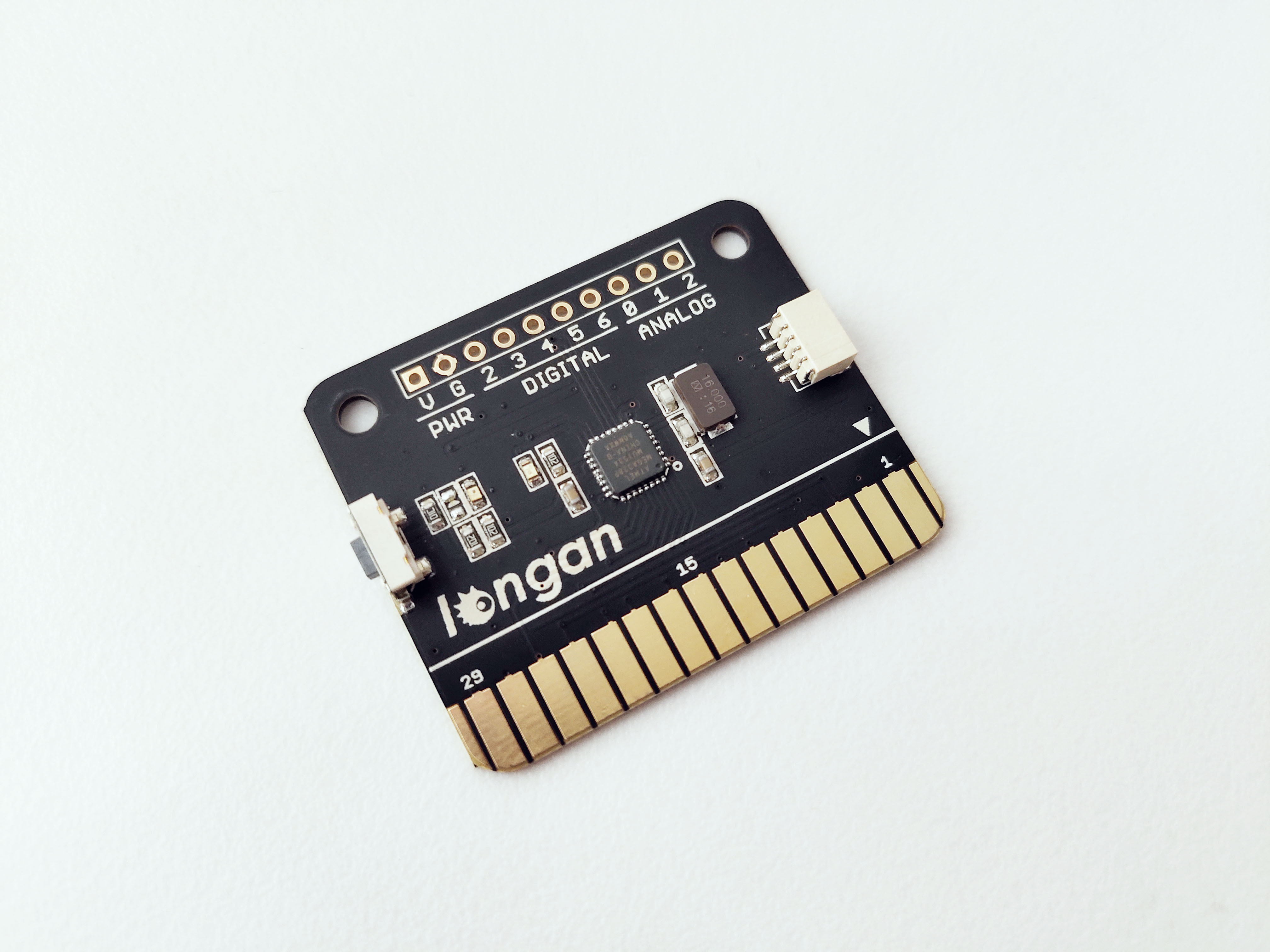
Here is a list of things that can be found on the front of the Carduino board.
- ATmega328P microprocessor
- Programmable LED – Connects with digital pin 13
- Reset button – Re-starts the Arduino sketch
- Gold fingers (Edge connector)
Specifications
- Measures 41mm x 33mm
- ATmega328P @16Mhz clock speed with 3.3V or 5V logic/power (datasheet: http://www.atmel.com/devices/atmega32u4.aspx)
- 32KB of flash memory which 4KB used by bootloader
- Programmable LED - emits blue light
- Power indicator LED -emits green light
- Preloaded with the Arduino UNO bootloader
- Edge connector (Golden fingers) exposes 30 pins (power, digital, analog, PWM, I2C, SPI, UART)
- Reset button
- Two mounting holes
- PH1.0 connector
Carduino comes with fully assembled and tested, with a USB interface that lets you quickly use it with the Arduino IDE.
Pins
Carduino 238P provides group of pins.
Gold Fingers / Edge Connector
The edge connector (gold fingers) has total of 30 contacts (each side has 15 contacts).
On the front side of the Carduino 328, a white arrow is printed near the edge connector indicates the pin #1. You can find some pin numbers printed on the edge connector itself (1, 15, and 29). You can count the pin numbers starting with 1 and count by twos from right to left would be 1, 3, 7, 9, 11, 15, 17, 19, 21, 23, 27, and 29. Notice that all the counts are odd numbers.
On the back side of the Carduino 328, you also can find some pin numbers printed on the edge connector itself (2, 16, and 30). You can count the pin numbers starting with 2 and count by twos from left to right would be 2, 4, 6, 8, 10, 12, 14, 16, 18, 20, 22, 24, 26, 28 and 30. Notice that all the counts are even numbers.
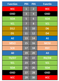
Table below presents the pin numbers and their functions. The pin functions of Carduino is exactly same with the pin functions of Arduino UNO.
Power connections
Carduino 328 can be powered through one of the boards with AAA battery card with 5V.
Following pins allow you to power the Carduino with batteries (AAA battery card) through one of the Longan boards.
- VCC – 5V regulated supply voltage (Front: pin #1, #29 / Back: pin #2, #30)
- GND – This is the common ground for all power and logic (Front: pin #3, #27 / Back: pin #4, #28)
You can also hack the power pins to power the Carduino 328 with a regulated 3.3V or 5V power source.
GPIO pins
This is the general purpose I/O pin set for the Carduino. GPIO consists of digital, analog, I2C, SPI, and UART pins. Most pins can do PWM output. Also, all pins can be used as interrupt pins.
- Digital (Front: pin #9, #11, #21 / Back: pin #10, #12, #22)
- Analog (Front: pin #13, #19 / Back: pin #14, #20)
I2C pins
You can use I2C pins allow Carduino 328 to communicate with all the Longan cards (all cards are I2C enabled and comes with a factory default unique I2C address).
- SDA – The I2C data pin (Front: pin #5, #25 / Back: pin #6, #26)
- SCL – The I2C clock pin (Front: pin #7, #23 / Back: pin #8, #24)
Hardware SPI pins
These are the hardware SPI pins that can be used to communicate with high speed.
- SCK – Serial Clock (Front: pin #17)
- MISO - Master In Slave Out, takes data from the Carduino to the SPI device (Front: pin #15)
- MOSI – Master Out Slave In, takes data to the Carduino from the SPI device (Back: pin #16)
Hardware UART / Serial
These pins can be used to connect devices support with UART using two wires.
- TX – Transmits data (Front: pin #21)
- RX – Receives data (Back: pin #22)
10-pin Connector
The 10-pin connector allows the Carduino to connect with sensors, actuators, and other devices.
Table below presents the type of pins of the 10-pin connector. The pin numbers are equivalent to the pin numbers of the Arduino UNO.
| Pin | Type |
|---|---|
| V | Power |
| G | Power |
| 2 | Digital |
| 3 | Digital |
| 4 | Digital |
| 5 | Digital |
| 6 | Digital |
| 0 | Analog |
| 1 | Analog |
| 2 | Analog |
Arduino IDE Setup
First download the Arduino IDE from https://www.arduino.cc/en/Main/Software. Arduino IDE can be installed and run on Windows, Linux, and Mac OS X operating systems. Download the installer or zip file (Windows only) and install (if you have the zip file, extract it to your Windows computer’s hard drive) it on your operating system.
Once finished, start the Arduino IDE.
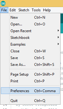
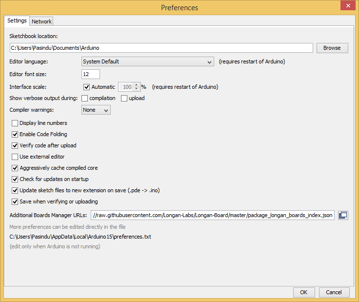
Copy and paste the link below into the Additional Boards Manager URLs option in the Arduino IDE preferences (File > Preferences).
https://raw.githubusercontent.com/Longan-Labs/Longan-Board/master/package_longan_boards_index.json
The Longan AVR boards supplied package includes supports for Longan Card, Carduino 328, Carduino 32U4.
Once done, click OK button to save the new preference settings.
Now open the Boards Manager by navigating to the Tools -> Board menu.
Select All from the Type drop-down menu. Then type longan in the top search bar. While typing, you will see the Longan AVR package.
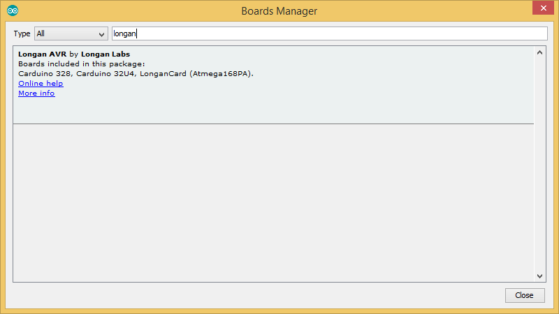
Click on the Longan AVR by Longan Labs and then click on Install button.
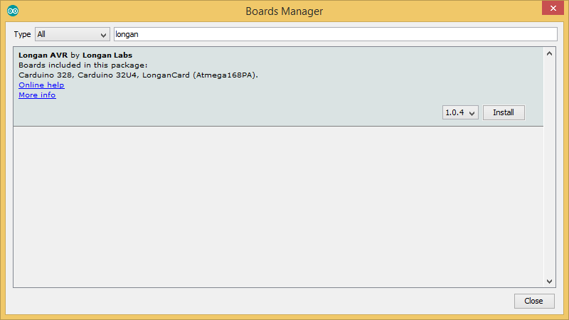
Once installed, close the Boards Manager window.
How to Use
Carduino 328 can be plugged in to one of the edge connector slots available in the following boards.
- Game board
- Car board
- Sensor display board
- Extension board
- Pi Hap
All Longan cards are polarized, and every pin is unique in terms of both location and function. On the front side of the Carduino, a white arrow is printed near the edge connector indicates the pin #1.
Using with Extension Board
We will be using Longan Extension board demonstrate how you can insert the Carduino 328 in to an edge connector slot.
Take the Carduino 328, programmer card, and Extension board.
Plug the Carduino 328 into one of the edge connector slots of the Extension board.
Also, plug the Programmer card into another edge connector slot of the Extension board.
Connect the Type-C USB cable to the USB connector of the Programmer card and connect the other end to your computer.
Blink
We will start off with something very simple with an LED, turning on and off, repeatedly, producing a pleasant blinking effect. The Carduino 328 has a built-in LED on digital pin 13 (Arduino UNO equivalent) emits bright blue light when turned on. You can find it on the front of the Carduino 328.
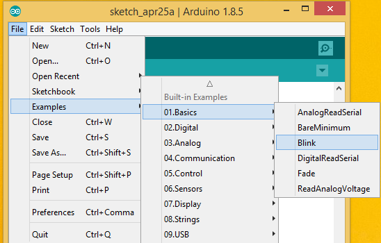
Now you can upload your first Blink sketch to the Carduino 328. The Arduino IDE provides a great example for blinking a LED. There is no need to type anything, just click File > Example > 01.Basics > Blink under Built-in Examples in the Arduino IDE.
Next, tell the Arduino IDE to use the Carduino. To do this, click Tools > Board > Arduino/Genuino UNOi under Longen AVR Boards.
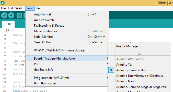
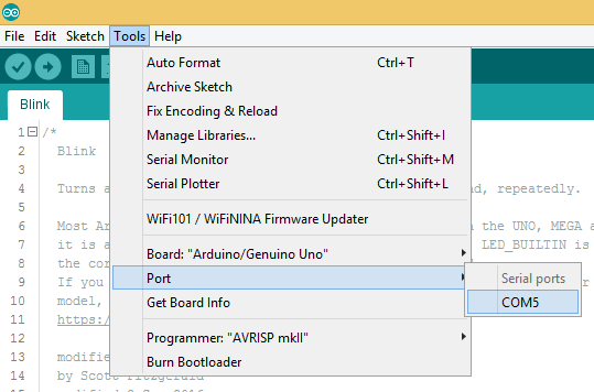
Then select the proper port in Tools > Port > (the Serial/COM port of your Carduino 238).
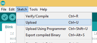
Next, upload the program by clicking Sketch > Upload.
It will take some time to compile and upload the sketch in to the Carduino.
If you have trouble loading the Blink sketch from the examples, you can copy and paste the code below into the Arduino editor.
/*
  Blink

  Turns an LED on for one second, then off for one second, repeatedly.

  Most Arduinos have an on-board LED you can control. On the UNO, MEGA and ZERO
  it is attached to digital pin 13, on MKR1000 on pin 6. LED_BUILTIN is set to
  the correct LED pin independent of which board is used.
  If you want to know what pin the on-board LED is connected to on your Arduino
  model, check the Technical Specs of your board at:
  https://www.arduino.cc/en/Main/Products

  modified 8 May 2014
  by Scott Fitzgerald
  modified 2 Sep 2016
  by Arturo Guadalupi
  modified 8 Sep 2016
  by Colby Newman

  This example code is in the public domain.

  http://www.arduino.cc/en/Tutorial/Blink
*/

// the setup function runs once when you press reset or power the board
void setup() {
  // initialize digital pin LED_BUILTIN as an output.
  pinMode(LED_BUILTIN, OUTPUT);
}

// the loop function runs repeatedly forever
void loop() {
  digitalWrite(LED_BUILTIN, HIGH);   // turn the LED on (HIGH is the voltage level)
  delay(1000);                       // wait for a second
  digitalWrite(LED_BUILTIN, LOW);    // turn the LED off by making the voltage LOW
  delay(1000);                       // wait for a second
}
After uploading the sketch to the Carduino 328, you should see the LED on the card is blinking.
Resources
- Eagle Files: https://github.com/Longan-Labs/EagleFile_Cards/tree/master/1013001_Carduino_328
- Longan AVR boards supplied package: https://raw.githubusercontent.com/Longan-Labs/Longan-Board/master/package_longan_boards_index.json
- Arduino IDE: https://www.arduino.cc/en/Main/Software
- Sample Arduino Code: https://github.com/Longan-Labs/LonganCard