OBD-II RF DEV KIT
INTRODUCTION
Usually there is an OBD-II interface on the vehicla, allowing the user to read some data through the CAN-Bus interface, such as vehicle speed, engin speed, oil temperature, etc. We have also made some OBD-II related products, such as OBD-II CAN-Bus GPS Dev Kit, which is able to store the data read through OBD-II to SD card.
During the use of OBD, an OBD-II cable is usually required to connect to the vehicle. Wiring is easy, but hiding the cable is hard. For this reason we designed this OBD-II RF Dev Kit.
This kit contains two parts, which we call the transmitter and receiver. The transmitter is inserted into the OBD-II interface of the vehicle, and the transmitter is integrated with CAN-Bus interface and RF communication, which can transmit the data read by CAN-Bus to the remote end through RF. The receiver is a Serial RF Module, which can send the data from the receiving end to the microcontroller through the serial port.
If you want to use OBD-II for some interesting projects, you can try this kit, you will not be disappointed.
CAN BUS PRODUCTS LIST OF LONGAN LABS

We have made a lot of can bus products, you can get more information through the following list, so as to choose a product suitable for you.
| PRODUCT NAME | LINK | PRICE | MCU | CHIP | PROTOCOL |
|---|---|---|---|---|---|
| Serial CAN Bus Module | LINK | $19.9 | ATMEGA168PA | MCP2515 | CAN2.0 |
| I2C CAN Bus Module | LINK | $19.9 | ATMEGA168PA | MCP2515 | CAN2.0 |
| OBD-II Serial CAN Bus Dev Kit | LINK | $20.9 | ATMEGA168PA | MCP2515 | CAN2.0 |
| OBD-II CAN Bus GPS Dev Kit | LINK | $29.9 | ATMEGA32U4 | MCP2515 | CAN2.0 |
| OBD-II CAN Bus Basic Dev Kit | LINK | $24.9 | ATMEGA32U4 | MCP2515 | CAN2.0 |
| CAN-FD Shield | LINK | $19.9 | NO MCU | MCP2517FD | CAN-FD |
| CAN Bus Shield | LINK | $9.9 | NO MCU | MCP2515 | CAN2.0 |
| CANBed | LINK | $24.9 | ATMEGA32U4 | MCP2515 | CAN2.0 |
| CANBed-FD | LINK | $29.9 | ATMEGA32U4 | MCP2517FD | CAN-FD |
| CANBed M4 | LINK | $49.9 | ATSAME51 | - | CAN-FD |
| OBD-II RF Dev Kit | LINK | $19.9 | ATmega168PA | MCP2515 | CAN2.0 |
Note
The above price may not be the latest price, please refer to the price on the product page.
FEATURES
- CAN2.0
- 2.4G RF module
- standard OBD-II connector
- Easy to use Arduino library
- 120 meters communication distance in the wild
SPECIFICATIONS
- MCU: Atmega168PA
- Barurate: 9600
- Communication distance: 120m
- Power input: 12V for the transmitter and 3.⅗V for the receiver
HARDWARE OVERVIEW
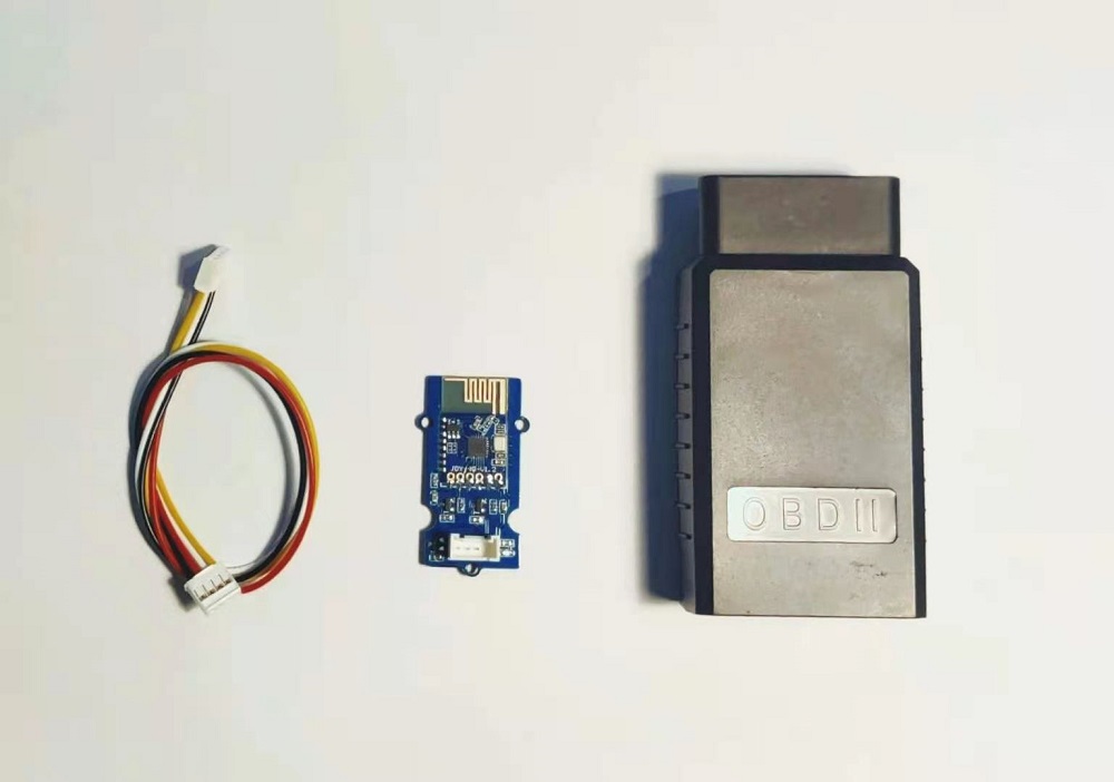
PART LIST
- The transmitter with a case
- The receiver module
- Grove Cable
USAGE
ARDUINO CODE
We provide an Arduino library for OBD-II RF Dev Kit.
There're many examples for the library, which is consist of,
- OBDII-PIDs - Get data from OBD-II interface
- send - Send a frame to CAN Bus
- recv - Receive a frame from CAN Bus
- set_mask_filter_recv - Receive a frame from CAN Bus with mask and filter setting
HOW TO GET DATA FROM VEHICLE
Here we provide an example of reading data from a vihicle. In order to simplify the process, we only read the speed and engin speed of the vehicle.
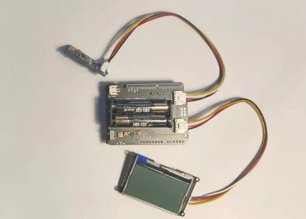
In addition to OBD-II RF Dev Kit, we also need some other modules to complete this application, we need to use the following modules:
- Longan Core 01: An Arduino UNO compatible board, priced at only $5.9
- AAA Battery Shield: This shiel use two AAA batteries to provide a stable 5V for Arduino
- I2C_LCD: A simple and easy-to-use display that communicates via I2C
Hardware Connection
First, we insert the AAA Battery Shield to Longan Core 01, then insert the I2C_LCD into the I2C port on the AAA Battery Shield, and insert the Serial RF module in the OBD-II RF Dev Kit into the A0 port.
As shown below:
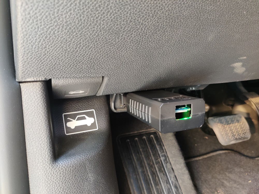
As for the transmitter, plug it into the OBD-II interface of your vehicle, as shown below:
Upload the code
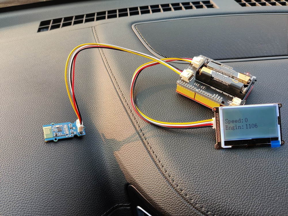
We procide an Arduino library for OBD-II RF Dev kit, you have to install the library first. You have to install the Library for I2C_LCD as well. Then, download the code for the demo, and upload it to Longan Core 01.
If nothing unexpected happens, there's should be values of speed and engin speed displaied on the LCD, as shown below:
If you want to read other parameters, you can refer to OBD-II_PIDs
AT Command
We can use AT commands to set up and control the transmitter. When using AT commands, we need to connect the transmitter to power, otherwise the command will not be received.
Note
The AT Command here is the same as the AT command of the Serial CAN Bus Module. If you have used the Serial CAN Bus Module, you will be familiar with these commands.
| CMD | Description |
|---|---|
| +++ | Switch from Normal mode to Config mode |
| AT+C=[value] | Set CAN Bus baud rate |
| AT+M=[N][EXT][value] | Set mask |
| AT+F=[N][EXT][value] | Set filter |
| AT+Q | Switch to Normal Mode |
Tips
All of the cmd should end with '\n' except +++
Set CAN Bus Baudrate
You can use this command to set the rate of CAN Bus, there's 18 rates available. Normally, if you want to hack your vehicle, 500k is the right one.
AT+C=[value]
| value | 01 | 02 | 03 | 04 | 05 | 06 | 07 | 08 | 09 | 10 | 11 | 12 | 13 | 14 | 15 | 16 | 17 | 18 |
|---|---|---|---|---|---|---|---|---|---|---|---|---|---|---|---|---|---|---|
| rate(kb/s) | 5 | 10 | 20 | 25 | 31.2 | 33 | 40 | 50 | 80 | 83.3 | 95 | 100 | 125 | 200 | 250 | 500 | 666 | 1000 |
Tip
For most vehicles, the baud rate of CANBus is 500kb/s, and a few cars are 1Mb/s
Eg: Set CAN BUS baud rate to 50K
AT+C=08
Respose
OK or ERROR
Set Mask
There're 2 Mask for the module, Mask0 and Mask1.
AT+M=[N][EXT][value]
N:
- 0: Mask0
- 1: Mask1
EXT:
- 0: Standard Frame
- 1: Extended Frame
value:
Neeed 8 bit of character, hexadecimal.
Eg: Set Mask1 to 0x3DF, standard frame:
AT+M=[1][0][000003DF]
Respose
OK or ERROR
Set Filt
There're 6 Mask for the module, Filt0 ~ Filt5
AT+F=[N][EXT][value]
N:
| N | 0 | 1 | 2 | 3 | 4 | 5 |
|---|---|---|---|---|---|---|
| Filt | Filt0 | Filt1 | Filt2 | Filt3 | Filt4 | Filt5 |
EXT:
- 0: Standard Frame
- 1: Extended Frame
value:
Neeed 8 bit of character, hexadecimal.
Eg: Set Filt3 to 0x2C, standard frame:
AT+F=[1][0][0000002C]
Respose
OK or ERROR
Working Mode
When the module working on Working mode (default mode), you can send and recevie data from CAN Bus.
Send
You should send 14 byte of data per frame. Defined as below,
| bit | 0 | 1 | 2 | 3 | 4 | 5 | 6 | 7 | 8 | 9 | 10 | 11 | 12 | 13 |
|---|---|---|---|---|---|---|---|---|---|---|---|---|---|---|
| define | ID3 | ID2 | ID1 | ID0 | EXT | RTR | DTA0 | DTA1 | DTA2 | DTA3 | DTA4 | DTA5 | DTA6 | DTA7 |
- ID0~ID3: CAN ID
- EXT: 0 for standard frame, 1 for extended frame
- RTR: 0 for standard frame, 1 for remote frame
- DTA0~DTA7: 8 byte of data
Eg.
Send {1, 2, 3, 4, 5, 6, 7, 8} to ID:0x3DC, Standard frame:
{0, 0, 3, 0xDC, 0, 0, 1, 2, 3, 4, 5, 6, 7, 8}
Recv
You will get 12 byte of data per frame. Defined as below,
| bit | 0 | 1 | 2 | 3 | 4 | 5 | 6 | 7 | 8 | 9 | 10 | 11 |
|---|---|---|---|---|---|---|---|---|---|---|---|---|
| define | ID3 | ID2 | ID1 | ID0 | DTA0 | DTA1 | DTA2 | DTA3 | DTA4 | DTA5 | DTA6 | DTA7 |
- ID0~ID3: CAN ID
- DTA0~DTA7: 8 byte of data
FAQ
How to find the tech support
Please feel free to contact joney.sui@longan-labs.cc if you need more help.