CANBED M0
INTRODUCTION
CAN Bus is a common industrial bus because of its long travel distance, medium communication speed and high reliability. It is commonly found on modern machine tools, such as an automotive diagnostic bus. CANBed M0 is an upgraded version of CANBed V1. CANBed M0 uses an MCU based on the Cortex M0 core and has richer resources than CANBed V1.
CANBED FAMILY
Currently we have 6 CANBeds, you can choose the right one according to your needs.
| VRESION | CANBed V1 | CANBed FD | CANBed M0 | CANBed M4 | CANBed RP2040 | CANBed Dual |
|---|---|---|---|---|---|---|
| MCU | Atmega32U4 | Atmega32U4 | ATSAMD21G18 | ATSAME51G19A | RP2040 | RP2040 |
| CORE | AVR 8 bit | AVR 8 bit | ARM Cortex M0+ 32bit | ARM Cortex M4 32bit | Dual ARM Cortex-M0+ | Dual ARM Cortex-M0+ |
| PROTOCOL | CAN2.0 | CANFD & CAN2.0 | CAN2.0 | CANFD & CAN2.0 | CAN2.0 | CANFD & CAN2.0 |
| CLOCK | 16MHz | 16MHz | 48MHz | 133MHz | 133MHz | 133MHz |
| FLASH | 32KB | 32KB | 256KB | 2MKB | 2MKB | 2MKB |
| RAM | 2.5KB | 2.5KB | 32KB | 192KB | 264KB | 264KB |
| PRICE | $24.9 | $29.9 | EoL | $49.9 | $15.9 | $24.9 |
| LINK | GET ONE | GET ONE | GET ONE | GET ONE | GET ONE | GET ONE |
Note
The above price may not be the latest price, please refer to the price on the product page.
CAN BUS PRODUCTS LIST OF LONGAN LABS

We have made a lot of can bus products, you can get more information through the following list, so as to choose a product suitable for you.
| PRODUCT NAME | LINK | PRICE | MCU | CHIP | PROTOCOL |
|---|---|---|---|---|---|
| Serial CAN Bus Module | LINK | $19.9 | ATMEGA168PA | MCP2515 | CAN2.0 |
| I2C CAN Bus Module | LINK | $19.9 | ATMEGA168PA | MCP2515 | CAN2.0 |
| OBD-II Serial CAN Bus Dev Kit | LINK | $20.9 | ATMEGA168PA | MCP2515 | CAN2.0 |
| OBD-II CAN Bus GPS Dev Kit | LINK | $29.9 | ATMEGA32U4 | MCP2515 | CAN2.0 |
| OBD-II CAN Bus Basic Dev Kit | LINK | $24.9 | ATMEGA32U4 | MCP2515 | CAN2.0 |
| CAN-FD Shield | LINK | $19.9 | NO MCU | MCP2517FD | CAN-FD |
| CAN Bus Shield | LINK | $9.9 | NO MCU | MCP2515 | CAN2.0 |
| CANBed | LINK | $24.9 | ATMEGA32U4 | MCP2515 | CAN2.0 |
| CANBed-FD | LINK | $29.9 | ATMEGA32U4 | MCP2517FD | CAN-FD |
| CANBed M4 | LINK | $49.9 | ATSAME51 | - | CAN-FD |
| OBD-II RF Dev Kit | LINK | $19.9 | ATmega168PA | MCP2515 | CAN2.0 |
Note
The above price may not be the latest price, please refer to the price on the product page.
FEATURES
- CAN2.0
- ATSAMD21G18 32bit Cortex M0 core (Arduino Zero bootloader)
- 256KB flash, 32KB RAM
- Industrial standard 9 pin sub-D connector or 4PIN Terminal Connector
- OBD-II and CAN standard pinout selectable at sub-D connector
- 2x4Pin Connector compatable with Grove system
- Size: 56x41mm
SPECIFICATIONS
- MCU: ARM Cortex-M0+ CPU running at up to 48MHz
- Clock speed: 48MHz
- Flash memory: 256KB
- RAM: 32KB
- Input voltage: 7~28V
- Output Current @ 5V: 1A
- Input interface: Sub-D or Terminal
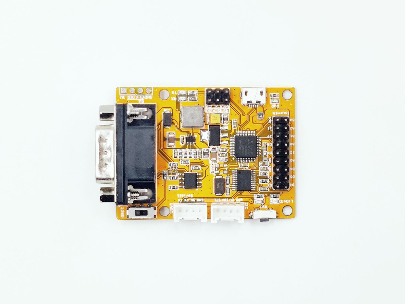
HARDWARE OVERVIEW
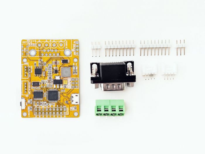
PART LIST
- CANBed M0 PCBA
- sub-D connector
- 4PIN Terminal
- 4PIN 2.0 Connector x 2
- 9x2 2.54 Header x 1
- 3x3 2.54 Header x 1
PIN OUT

1.9x2 IO Pin OUT:
The IO of ATSAMD21G18 is listed out here.
Note
The RX/TX use Serial2 in the code here
2.ATSAM21G18A:
Cortex M0+ core controller
2.Reset Button:
Reset the on-board Atmega chip.
3.Micro USB connector for programming
4. SPI interface
5.CAN RX/TX Indicator
6.sub-D connector or Terminal for CAN Bus
D-Sub CANbus PinOut
| pin# | Signal names | Signal Description |
|---|---|---|
| 1 | Reserved | Upgrade Path |
| 2 | CAN_L | Dominant Low |
| 3 | CAN_GND | Ground |
| 4 | Reserved | Upgrade Path |
| 5 | CAN_SHLD | Shiled, Optional |
| 6 | GND | Ground,Optional |
| 7 | CAN_H | Dominant High |
| 8 | Reserved | Upgrade Path |
| 9 | CAN_V+ | Power, Optional |
7.Switch for the 120Ω terminal resistor for CAN Bus

If you use this board on the end of the CAN bus, please put this switch to 120Ω. For more detail about the CAN bus protocol, please refer to the NI CAN Physical Layer and Termination Guide
8.Grove connector for UART
Note
Use Serial1 in the code
9.Grove connector for I2C
A.Reset Button
B.User LED, connected to D13
DB9 connector
The DB9 interface of CAN Bus has two different protocols, OBD and CAN Open. Their definition is as follows,
| pin# | OBD(default) | CAN OPEN |
|---|---|---|
| 1 | GND | N.C |
| 2 | GND | CAN_L |
| 3 | CANH | GND |
| 4 | N.C | N.C |
| 5 | CANL | GND |
| 6 | N.C | N.C |
| 7 | N.C | CAN_H |
| 8 | N.C | N.C |
| 9 | CAN_V+ | CAN_V+ |
If you want to use the OBD protocol, you don't need to make any changes to the hardware.
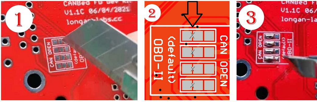
If you need to use the CAN Open protocol, first we look at the back side of the PCB board, you can see the Pads below,
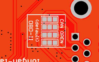
These pads are connected to the OBD side by default. We have to prepare a knife to disconnect the OBD side, and then use an electric soldering iron to solder the CAN Open side of the pads.
ARDUINO IDE SETUP
First download the Arduino IDE from https://www.arduino.cc/en/Main/Software. Arduino IDE can be installed and run on Windows, Linux, and Mac OS X operating systems. Download the installer or zip file (Windows only) and install (if you have the zip file, extract it to your Windows computer’s hard drive) it on your operating system.
Once finished, start the Arduino IDE.
Copy and paste the link below into the Additional Boards Manager URLs option in the Arduino IDE preferences (File > Preferences).
https://raw.githubusercontent.com/Longan-Labs/Longan-SAMD-Boards/master/package_longan_m0_boards_index.json
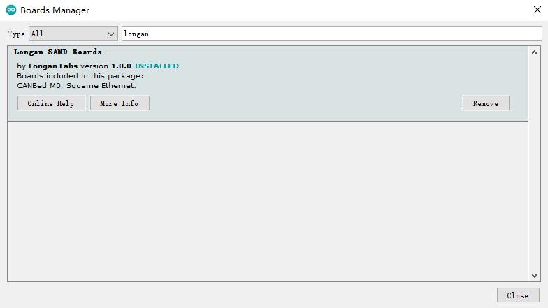
Enter longan to install the latest Longan SAMD board
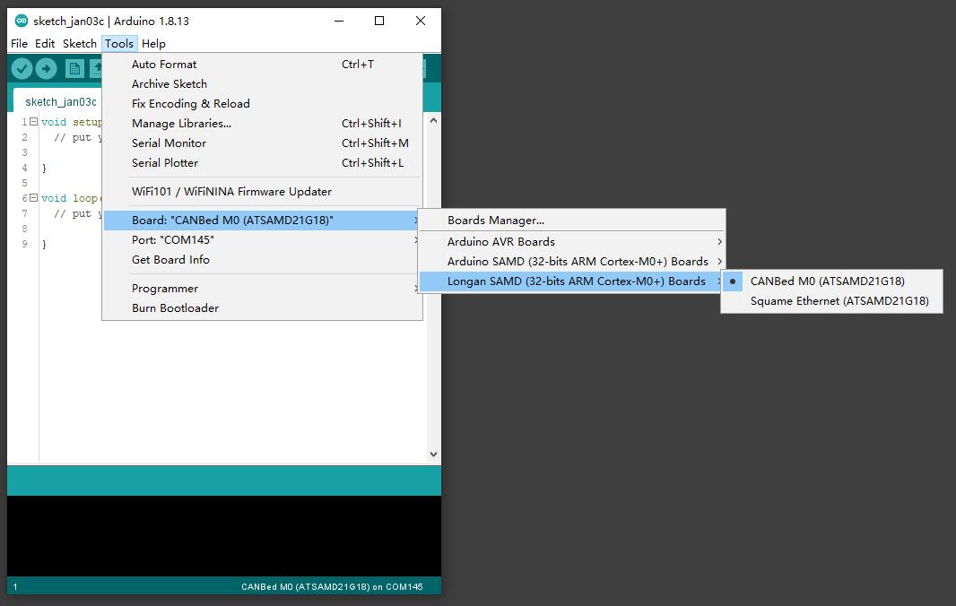
Then you can select the CANBed M0 board,
USAGE
ARDUINO CODE
We provide an Arduino library for CANBed.
Note
Please change the SPI_CS_PIN to 3 for CANBed M0
There're many examples for the library, which is consist of,
- OBDII-PIDs - Get data from OBD-II interface
- send - Send a frame to CAN Bus
- recv - Receive a frame from CAN Bus
- set_mask_filter_recv - Receive a frame from CAN Bus with mask and filter setting
APIS
1. SET THE BAUD RATE
This function is used to initialize the baud rate of the CAN Bus system.
The available baud rates are listed as follows:
#define CAN_5KBPS    1
#define CAN_10KBPS   2
#define CAN_20KBPS   3
#define CAN_25KBPS   4
#define CAN_31K25BPS 5
#define CAN_33KBPS   6
#define CAN_40KBPS   7
#define CAN_50KBPS   8
#define CAN_80KBPS   9
#define CAN_83K3BPS  10
#define CAN_95KBPS   11
#define CAN_100KBPS  12
#define CAN_125KBPS  13
#define CAN_200KBPS  14
#define CAN_250KBPS  15
#define CAN_500KBPS  16
#define CAN_666kbps  17
#define CAN_1000KBPS 18
2. SET RECEIVE MASK AND FILTER
There are 2 receive mask registers and 5 filter registers on the controller chip that guarantee you getting data from the target device. They are useful especially in a large network consisting of numerous nodes.
We provide two functions for you to utilize these mask and filter registers. They are:
Mask:
init_Mask(unsigned char num, unsigned char ext, unsigned char ulData);
Filter:
init_Filt(unsigned char num, unsigned char ext, unsigned char ulData);
- num represents which register to use. You can fill 0 or 1 for mask and 0 to 5 for filter.
- ext represents the status of the frame. 0 means it's a mask or filter for a standard frame. 1 means it's for a extended frame.
- ulData represents the content of the mask of filter.
3. CHECK RECEIVE
The MCP2515 can operate in either a polled mode, where the software checks for a received frame, or using additional pins to signal that a frame has been received or transmit completed.
Use the following function to poll for received frames.
INT8U MCP_CAN::checkReceive(void);
The function will return 1 if a frame arrives, and 0 if nothing arrives.
4. GET CAN ID
When some data arrive, you can use the following function to get the CAN ID of the "send" node.
INT32U MCP_CAN::getCanId(void)
5. SEND A FRAME
CAN.sendMsgBuf(INT8U id, INT8U ext, INT8U len, data_buf);
It is a function to send data onto the bus. In which:
- id represents where the data comes from.
- ext represents the status of the frame. '0' means standard frame. '1' means extended frame.
- len represents the length of this frame.
- data_buf is the content of this message.
For example, In the 'send' example, we have:
unsigned char stmp[8] = {0, 1, 2, 3, 4, 5, 6, 7};
CAN.sendMsgBuf(0x00, 0, 8, stmp); //send out the message 'stmp' to the bus and tell other devices this is a standard frame from 0x00.
6. RECEIVE A FRAME
The following function is used to receive data on the 'receive' node:
CAN.readMsgBuf(unsigned char len, unsigned char buf);
In conditions that masks and filters have been set. This function can only get frames that meet the requirements of masks and filters.
- len represents the data length.
- buf is where you store the data.
FAQ
The RX/TX led light up and never turn off
- Check if the baudrate of CAN Bus is setting correct
- Try turning on/off the switch for the terminal resistor
- Cehck if CANH and CANL is connected correct
How to find the tech support
Please feel free to contact joney.sui@longan-labs.cc if you need more help.