CANBED FD
Introduction
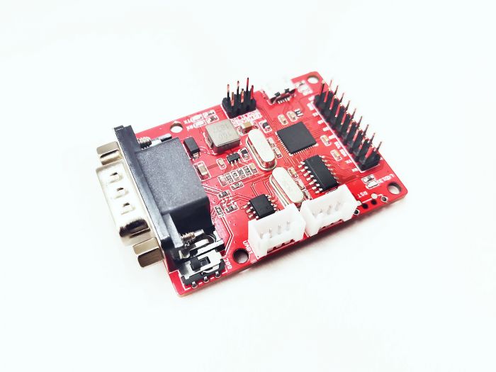
CANBed FD is a CAN FD dev board with Atmega32U4 microcontroller inside, which has 32KB of Flash and 2.5KB of RAM. The operating frequency is 16MHz, which can meet most embedded applications. There's Arduino Leonardo bootloader inside the Atmega32U4. If you have used the Arduino IDE, programming will not be a problem for you. You can also use AVR Studio for development, we provide ICSP interface.
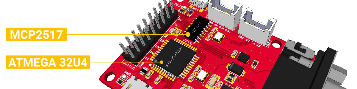
CANBed FD uses MCP2517FD as CAN controller and MCP2542 (MCP2557) as CAN receiver, chich are high-performance CAN Bus chip, can work in both CAN 2.0 and CAN FD protocols at the same time. There is a Micro USB connector on the board, through which you can program the board or supply power to the board.There are one I2C, one UART, one SPI interface, 3 analog input interfaces and 8 digital IO on the board.
We use a flexible way for CAN interface. You can use 4PIN Terminal or DB9 connector. DB9 connector uses OBD-II mode by default. You can also configure CAN Open mode on the hardware. The voltage input range of the CAN interface is 9-28V, which can provide a stable 5V/1A output.
If you want to use this board to develop OBD related applications, click to get a DB9 to OBD-II cable.
Note
For transportation considerations, the plug-in components of the kit are not soldered by default. After you receive the kit, you need to do some soldering work. If necessary, you can also contact info@longan-labs.cc after purchasing the board, then we can send it to you after the board is soldered well.
Application Ideas
With CANBed FD Dev board, you can,
- To learn CAN Bus and CAN FD communication
- To build product prototypes. After you complete the product prototype, we can help you integrate it into a product and assist you in production
- To read the data from the car
- As a part of your product, you don't need to design the MCU and CAN Bus separately, only need to complete other hardware design
CANBed Family
Currently we have 6 CANBeds, you can choose the right one according to your needs.
| VRESION | CANBed V1 | CANBed FD | CANBed M0 | CANBed M4 | CANBed RP2040 | CANBed Dual |
|---|---|---|---|---|---|---|
| MCU | Atmega32U4 | Atmega32U4 | ATSAMD21G18 | ATSAME51G19A | RP2040 | RP2040 |
| CORE | AVR 8 bit | AVR 8 bit | ARM Cortex M0+ 32bit | ARM Cortex M4 32bit | Dual ARM Cortex-M0+ | Dual ARM Cortex-M0+ |
| PROTOCOL | CAN2.0 | CANFD & CAN2.0 | CAN2.0 | CANFD & CAN2.0 | CAN2.0 | CANFD & CAN2.0 |
| CLOCK | 16MHz | 16MHz | 48MHz | 133MHz | 133MHz | 133MHz |
| FLASH | 32KB | 32KB | 256KB | 2MKB | 2MKB | 2MKB |
| RAM | 2.5KB | 2.5KB | 32KB | 192KB | 264KB | 264KB |
| PRICE | $24.9 | $29.9 | EoL | $49.9 | $15.9 | $24.9 |
| LINK | GET ONE | GET ONE | GET ONE | GET ONE | GET ONE | GET ONE |
Note
The above price may not be the latest price, please refer to the price on the product page.
CAN BUS PRODUCTS LIST OF LONGAN LABS

We have made a lot of can bus products, you can get more information through the following list, so as to choose a product suitable for you.
| PRODUCT NAME | LINK | PRICE | MCU | CHIP | PROTOCOL |
|---|---|---|---|---|---|
| Serial CAN Bus Module | LINK | $19.9 | ATMEGA168PA | MCP2515 | CAN2.0 |
| I2C CAN Bus Module | LINK | $19.9 | ATMEGA168PA | MCP2515 | CAN2.0 |
| OBD-II Serial CAN Bus Dev Kit | LINK | $20.9 | ATMEGA168PA | MCP2515 | CAN2.0 |
| OBD-II CAN Bus GPS Dev Kit | LINK | $29.9 | ATMEGA32U4 | MCP2515 | CAN2.0 |
| OBD-II CAN Bus Basic Dev Kit | LINK | $24.9 | ATMEGA32U4 | MCP2515 | CAN2.0 |
| CAN-FD Shield | LINK | $19.9 | NO MCU | MCP2517FD | CAN-FD |
| CAN Bus Shield | LINK | $9.9 | NO MCU | MCP2515 | CAN2.0 |
| CANBed | LINK | $24.9 | ATMEGA32U4 | MCP2515 | CAN2.0 |
| CANBed-FD | LINK | $29.9 | ATMEGA32U4 | MCP2517FD | CAN-FD |
| CANBed M4 | LINK | $49.9 | ATSAME51 | - | CAN-FD |
| OBD-II RF Dev Kit | LINK | $19.9 | ATmega168PA | MCP2515 | CAN2.0 |
Note
The above price may not be the latest price, please refer to the price on the product page.
Features
- Arduino Leonardo bootloader
- Work at CAN-FD and CAN 2.0
- Industrial standard 9 pin sub-D connector or 4PIN Terminal.
- OBD-II and CAN standard pinout selectable at sub-D connector
- 2x4Pin Connector compatable with Grove system from Seeedstudio
- SPI Interface up to 10 MHz
- Power input from 9-28V
- Output Current @ 5V: 1A
Specifications
| Parameter | Value |
|---|---|
| MCU | Atmega32U4 (with Arduino Leonardo bootloader) |
| Clock Speed | 16MHz |
| Flash Memory | 32KB |
| SRAM | 2.5KB |
| EERROM | 1KB |
| Operate Voltage | 7-28V |
| Input Interface | sub-D or 4PIN Terminal |
Hardware Overview
Part List
Note
In consideration of convenient transportation and cost reduction, there are some materials that you need to solder by hand. If you don't have soldering iron tools, you can also ask our engineers to do it for you. After you place an order, email info@longan-labs.
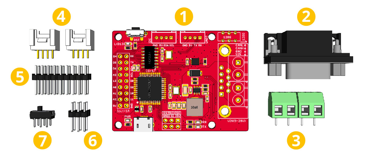
- CANBed-FD PCBA
- sub-D connector
- 4PIN Terminal
- 4PIN 2.0 Connector x 2
- 9x2 2.54 Header x 1
- 3x3 2.54 Header x 1
- Switch for 120Ω terminal resistor
Pin out
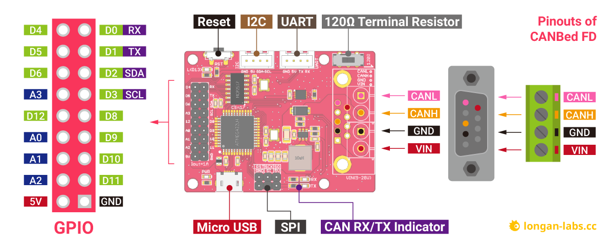
1. GPIO - 9x2 I/O Pin OUT:
The I/O of Atmega32U4 is list out here, which is consist of,
- 1 x UART (Serial1)
- 1 x I2C
- 4 x Analog Input(can be used us Digital IO)
- 8 x Digital I/O
2. Micro USB connector for programming
If you use Arduino IDE program the board, you need a micro USB cable to connect the board to PC.
3. SPI - ICSP connector
If you use AVR Studio to program the board, you can use this ICSP connector, and it can be used as SPI interface.
4. CAN RX/TX Indicator
When CAN Bus is transmitting data, these two leds blink.
5. DB9 connector or Terminal for CAN Bus
6. Switch for the 120Ω terminal resistor for CAN Bus

If you use this board on the end of the CAN bus, please put this switch to 120Ω. For more detail about the CAN bus protocol, please refer to the NI CAN Physical Layer and Termination Guide
7. Grove connector for UART
Use Serial1 in the code
8.Grove connector for I2C
9. Reset
Click to reset the board.
DB9 connector
The DB9 interface of CAN Bus has two different protocols, OBD and CAN Open. Their definition is as follows,
| pin# | OBD(default) | CAN OPEN |
|---|---|---|
| 1 | GND | N.C |
| 2 | GND | CAN_L |
| 3 | CANH | GND |
| 4 | N.C | N.C |
| 5 | CANL | GND |
| 6 | N.C | N.C |
| 7 | N.C | CAN_H |
| 8 | N.C | N.C |
| 9 | CAN_V+ | CAN_V+ |
If you want to use the OBD protocol, you don't need to make any changes to the hardware.
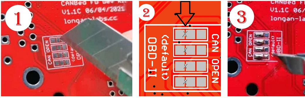
If you need to use the CAN Open protocol, first we look at the back side of the PCB board, you can see the Pads below,
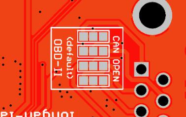
These pads are connected to the OBD side by default. We have to prepare a knife to disconnect the OBD side, and then use an electric soldering iron to solder the CAN Open side of the pads.
Getting Started
Here we use the Arduino IDE as a demonstration, through this chapter you can learn how to get started with CANBed FD. You need a micro USB cable to connect the CANBed FD Dev board to the computer.
IDE and Driver
There's Arduino leonardo bootloader in the board.
Click to get the latest Arduino IDE.
There's Arduino Leonardo driver in the folder: Arduino/drivers.
Download the install the library
Click to get the Arduino Library for CANBed FD Dev board.
In the Arduino IDE, navigate to Sketch > Include Library > Add .ZIP Library to install the Library.
Open the code and upload it to the board
Open the Arduino IDE, here we open the CAN20_Send example. This example can continuously send data to the CAN Bus.
// MCP2517/8 send a CAN frame
// CAN FD Shield - https://www.longan-labs.cc/1030012.html
// CANBed FD - https://www.longan-labs.cc/1030009.html

#include <SPI.h>
#include "mcp2518fd_can.h"

// pins for CAN-FD Shield
//const int SPI_CS_PIN = 9;
//const int CAN_INT_PIN = 2;

// pins for CANBed FD
const int SPI_CS_PIN = 17;
const int CAN_INT_PIN = 7;

mcp2518fd CAN(SPI_CS_PIN); // Set CS pin

void setup() {
    Serial.begin(115200);
    while(!Serial){};

    while (CAN_OK != CAN.begin(CAN_500KBPS)) {             // init can bus : baudrate = 500k
        Serial.println("CAN init fail, retry...");
        delay(100);
    }
    Serial.println("CAN init ok!");
}

unsigned char stmp[8] = {0, 1, 2, 3, 4, 5, 6, 7};

void loop() {

    CAN.sendMsgBuf(0x01, 0, 8, stmp);
    delay(10);
    CAN.sendMsgBuf(0x04, 0, 8, stmp);
    delay(500);                       // send data per 100ms
    Serial.println("CAN BUS sendMsgBuf ok!");
}

// END FILE
You need to select Arduino Leonardo on the Arduino IDE boards and select the correct COM port. Then you can upload the program to the CANBed FD Dev board by pressing the Upolading button on Arduino IDE.
Get data from a Vehicle
We can use CANBed to get data from a vehicle, we take the vehicle speed for an example here.
You can use our products to read data from cars. Here we provide a simple example by which you can read the speed and revs from a car. This is the OBD-based PIDs protocol. Regarding the deeper technology of OBD, we can't provide support at present. You may need to have some understanding of the car's protocol. After all, we are more of a hardware supplier.
The interface of OBD is as follows,
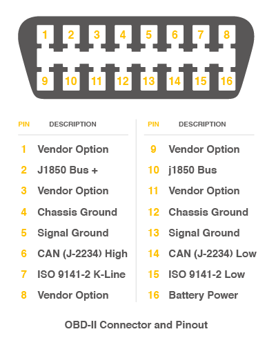
There're 4 pins we need to connect.
| OBD Pin | CANBed PIN |
|---|---|
| 5. Signal Ground | GND |
| 6. CAN(J-2234) High | CANH |
| 14. CAN(J-2234) Low | CANL |
| 16. Battery Power | VIN |
You can also use our OBD-II to DB9 Cable, which is very convenient to connect to OBD.
Upload the following code to the development board, then open the serial monitor, you get the speed from the car now.
#include <SPI.h>
#include "mcp2518fd_can.h"

// pin for CAN-FD Shield
//const int SPI_CS_PIN = 9;
//const int CAN_INT_PIN = 2;

// pin for CANBed FD
const int SPI_CS_PIN = 17;
const int CAN_INT_PIN = 7;

mcp2518fd CAN(SPI_CS_PIN); // Set CS pin

#define PID_ENGIN_PRM       0x0C
#define PID_VEHICLE_SPEED   0x0D
#define PID_COOLANT_TEMP    0x05

#define CAN_ID_PID          0x7DF

unsigned char PID_INPUT;
unsigned char getPid    = 0;

void set_mask_filt() {
    CAN.init_Filt_Mask(0, 0, 0x7E8, 0x7FC);
}

void sendPid(unsigned char __pid) {
    unsigned char tmp[8] = {0x02, 0x01, __pid, 0, 0, 0, 0, 0};
    CAN.sendMsgBuf(CAN_ID_PID, 0, 8, tmp);
}

bool getSpeed(int *s)
{
    sendPid(PID_VEHICLE_SPEED);
    unsigned long __timeout = millis();

    while(millis()-__timeout < 1000)      // 1s time out
    {
        unsigned char len = 0;
        unsigned char buf[8];

        if (CAN_MSGAVAIL == CAN.checkReceive()) {                // check if get data
            CAN.readMsgBuf(&len, buf);    // read data,  len: data length, buf: data buf

            if(buf[1] == 0x41)
            {
                *s = buf[3];
                return 1;
            }
        }
    }

    return 0;
}

void setup() {
    Serial.begin(115200);
    while(!Serial);

    while (CAN_OK != CAN.begin(CANFD_500KBPS)) {             // init can bus : baudrate = 500k
        Serial.println("CAN init fail, retry...");
        delay(100);
    }
    Serial.println("CAN init ok!");
    set_mask_filt();
}

void loop() {

    int __speed = 0;
    int ret = getSpeed(&__speed);
    if(ret)
    {
        Serial.print("Vehicle Speed: ");
        Serial.print(__speed);
        Serial.println(" kmh");
    }
    delay(500);
}

// END FILE
Arduino Library
We provide an Arduino library for CANBed-FD.
Note
Change the CS pin to 17, INT pin to 7
There're many examples for the library, which is consist of,
- CAN20_RECV_CHECK - Receive a CAN2.0 frame with check mode
- CAN20_RECV_INT - Receive a CAN2.0 frame with interrupt mode
- CAN20_RECV_MASK_FILT - Receive a CAN2.0 frame with mask/filter setting
- CAN20_SEND - Send a frame to CAN Bus at CAN 2.0
- CANFD_RECV_CHECK - Receive a CAN FD frame with check mode
- CANFD_RECV_INT - Receive a CAN FD frame with interrupt mode
- CANFD_RECV_MASK_FILT - Receive a CAN FD framw with mask/filter setting
- CANFD_SEND - Send a CAN FD frame
- OBDII_PIDs - Get data from a vehicle
Note
For more details about each demo, you can open the demo code, and we have made detailed comments in the code.
FAQ
I can't upload code to CANBed FD
- When the board is connected to the computer via the Micro USB cable, a new COM device will appear on the computer. If the new device does not appear on your computer, you can try a different USB cable or try another computer.
- If your PC recognize the COM port, please try pressing the reset button, then click on the Upload button in Arduino IDE, when the IDE shows compile done, release the reset button immediately.*
The RX/TX led light up and never turn off
- Check if the baudrate of CAN Bus is setting correct
- Try turning on/off the switch for the 120Ω terminal resistor
- Check if CANH and CANL is well connected
How to find the tech support
Please contact support@longan-labs.cc for technical support. Our technical support engineer will usually reply you within 24 hours on working days. In order to get faster support, we hope that when you send us an email, you need to include at least the following content,
- When and how to buy the product
- Product version information
- Take a high-definition picture of the product you use, including the connection
- Describe in detail the problem you encountered and what kind of help you would like to get