BME280 Card
Introduction
The BME280 card features BOSCH BME280 sensor which provides humidity, pressure, and temperature.
The BME280 card provides following sensors through the Software I2C.
- Temperature
- Humidity
- Pressure
- Altitude
The altitude is calculated on the fly.
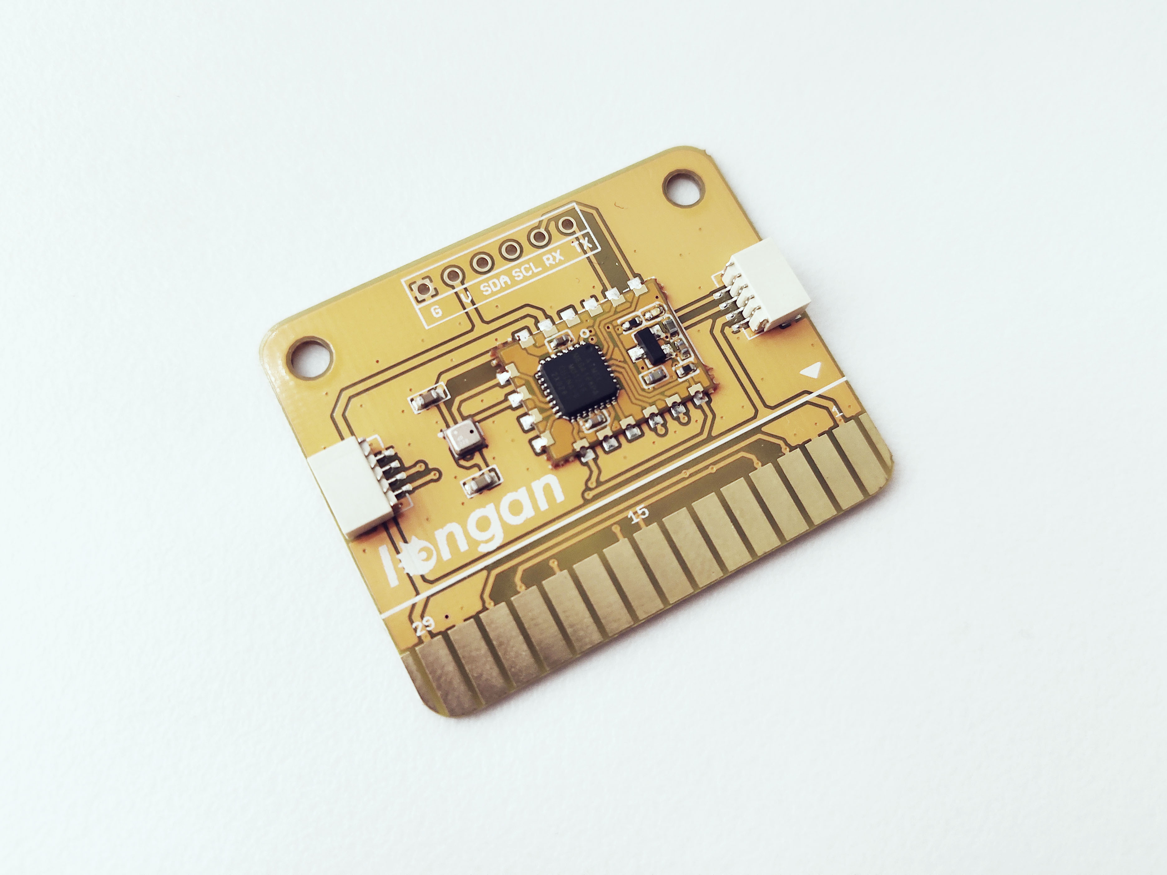
The front side of the BME280 card has following things.
- BME280 – has 3 sensors for temperature, humidity, and preassue
- ATmega 168PA microprocessor – runs card firmware
- 30 gold fingers – connects with any Longan board
- LED indicator – flashes when Carduino read/write data to the card via I2C
- Two 4 pin SH1.0 connectors – allows you to connect with MCUs or cards using dupont cables and communicates via I2C.
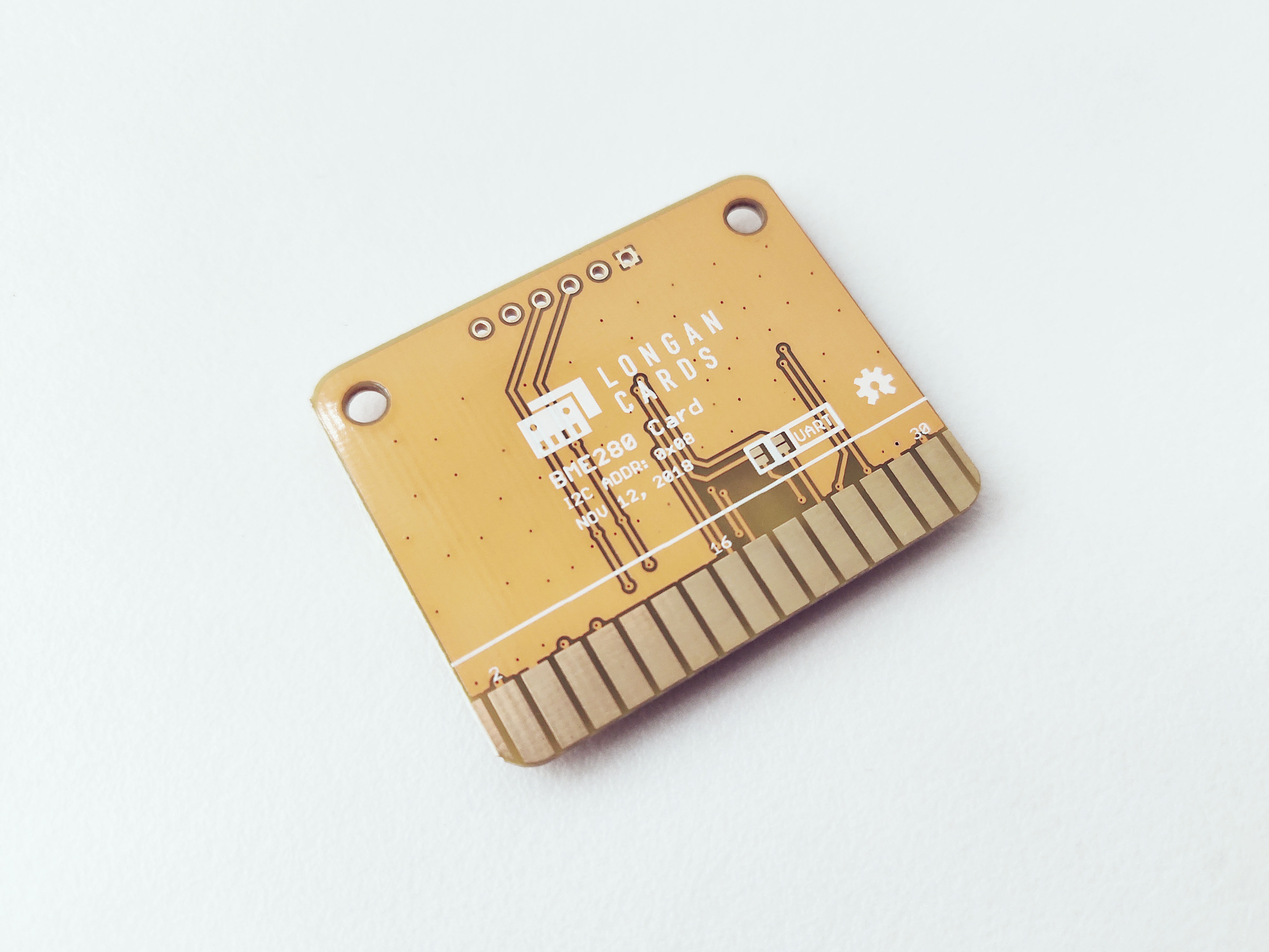
I2C Address
The default I2C address of the BME card is printed on the back side which is 0x08. However, you can modify it to a different address with the card firmware.
The BME280 card has an ATmaga168PA microprocessor running the card firmware (https://github.com/Longan-Labs/Card_Firmware/tree/master/SKU1011008_BME280_Card). The card firmware reads data from the BME280 (from all 3 sensors; temperature, humidity, and pressure) and write to the I2C bus using Software I2C.
The BME280 card works as an I2C slave device. You can use Wire library (https://www.arduino.cc/en/reference/wire) to read data from the card. The data can be retrieved from the ‘Sensor value' registers ranging from 0x30 – 0x33F. Each sensor value returns 4 bytes. Following figure presents the Sensor value format. Each sensor has its own data format as shown in the following figure.
Pins
The edge connector (gold fingers) has total of 30 contacts (each side has 15 contacts).
On the front side of the BME280 card, a white arrow is printed near the edge connector indicates the pin #1. You can find some pin numbers printed on the edge connector itself (1, 15, and 29). You can count the pin numbers starting with 1 and count by twos from right to left would be 1, 3, 7, 9, 11, 15, 17, 19, 21, 23, 27, and 29. Notice that all the counts are odd numbers.
On the back side of the BME280 card, you also can find some pin numbers printed on the edge connector itself (2, 16, and 30). You can count the pin numbers starting with 2 and count by twos from left to right would be 2, 4, 6, 8, 10, 12, 14, 16, 18, 20, 22, 24, 26, 28 and 30. Notice that all the counts are even numbers.
I2C
Following pins can be used for I2C communication. The I2C bus requires two wires to communicate with the device, a serial data line (SDA) and a serial clock line (SCL).
- SDA: Digital I/O, I2C bus serial bidirectional data line (Front: pin #5, #25 / Back: pin #6, #26)
- SCL: Digital Input, I2C bus serial clock input (Front: pin #7, #23 / Back: pin #8, #24)
Power
Following pins connect with the common power bus of a board.
- VCC: Power supply (Front: pin #1, #29 / Back: pin #2, #30)
- GND: To be connected to the system ground (Front: pin #3, #27 / Back: pin #4, #28)
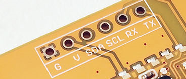
I2C and UART Test Point
You can solder a break away header (straight, 0.1” pin spacing) to the I2C and UART test point. You can connect any I2C device with SAL and SCL pins. You can also connect a device has a serial port with RX and TX pins. The VCC and GND pins can be used to power any device requires 5V to operate.
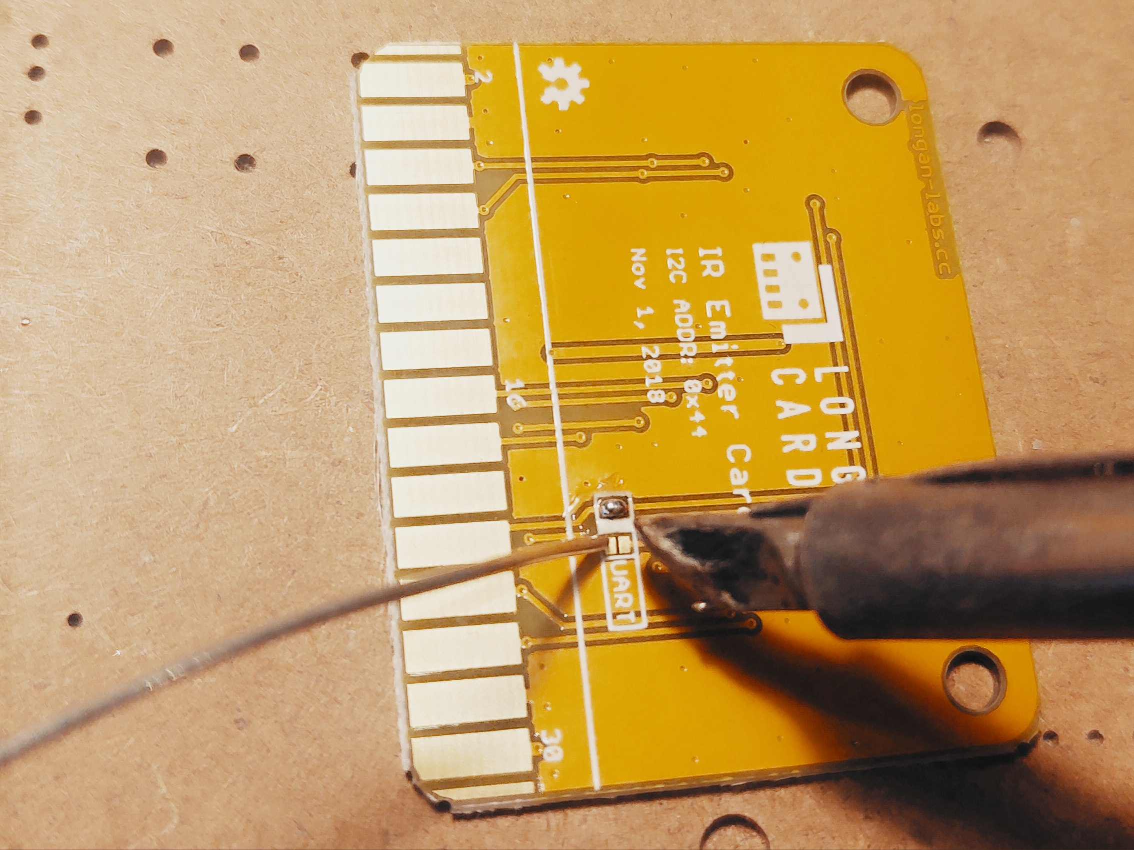
Updating Card Firmware
There may be times when you may want to update the card firmware. If that's the case, this section will show you how to do it.
- Take the BME280 card and solder the two UART pads on the back side.
- Plug the BME280 card into one of the edge connector slots of the Extension board.
- Connect the Extension board with your computer using a Type-C USB cable.
- Download the card firmware from https://github.com/Longan-Labs/Card_Firmware/tree/master/SKU1011008_BME280_Card
- Open the firmware file named SKU1011008_BME280_Card.ino with the Arduino IDE.
- Choose Tools > Board > LonganCard (Atmega 168PA)
- Choose Tools > Port > (the Serial/COM port of your Atmega 168PA).
- clicking Sketch > Upload.
It will take some time to compile and upload the sketch into the ATmega 168PA.
How to Use
The BME280 card can be plugged into an edge connector slot of one of the following Longan boards.
- Game board
- Car board
- Sensor board
- Extension board
- Pi Hap
When you plug, the white arrow head printed on the card should be pointing toward the white arrow head printed near the edge connector slot of the board. Once plugged, it can communicate with the Carduino through the I2C bus line of the board. It will also connect to the common power bus of the board.
Getting Ready
You can use the extension board to connect any Longan card with the Carduino.
-
First take the Extension board.
-
Next, plug the BME280 card in to one of the edge connector slot.
-
Then plug the Carduino in to another edge connector slot.
-
Finally, connect the extension board with your computer using a Type-C USB cable (you can use either USB connector on the Carduino or the Extension board).
Reading Senosr Data
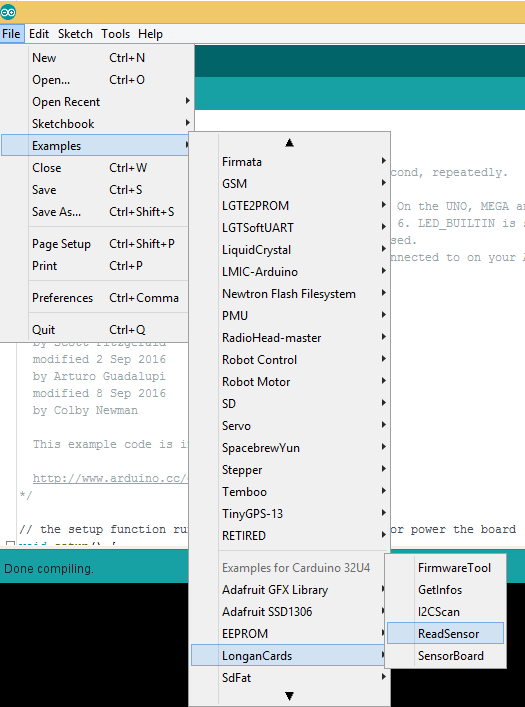
The sample code can be loaded to your Arduino IDE by clicking on File > Examples > LonganCards > ReadSensor.
If you have trouble loading the ReadSensor sketch from the examples, you can copy and paste the code below into the Arduino editor.
#include <Wire.h>
#include "CardsDfs.h"
#include "LonganCards.h"

CARD_INFO card;

int addr = 0;
int cntSensor = 0;

float sensorValue[10];

float str2num(unsigned char *str)
{
    float num = 0;
    memcpy((unsigned char *)(&num), str, 4);
    return num;
}

void setup() {
    // put your setup code here, to run once:
    Serial.begin(115200);
    Wire.begin();

    while(!Serial.available());

    addr = card.scan();
    if(0 == addr)
    {
        Serial.println("NO DEVICE!");
        while(1);
    }

    card.getInfo();
    card.disp();

    cntSensor = card.senCnt;
}

void loop()
{
    for(int i=0; i<cntSensor; i++)
    {
        sensorValue[i] = getValue(i);
        Serial.print(sensorValue[i], 2);
        Serial.print('\t');
    }

    Serial.println();
    delay(100);
}

float getValue(int s)
{
    unsigned char dta[10];
    unsigned long len = 0;

    Wire.beginTransmission(addr);
    Wire.write(REG_VALUE_START+s);      // ADDR_DATA_START = 0x30
    Wire.endTransmission();

    delay(1);
    Wire.requestFrom(addr, 6);

    delay(1);

    while(Wire.available())
    {
        dta[len++] = Wire.read();
    }

    return str2num(&dta[1]);
}

// END FILE
Connect the Type-C USB cable to the USB connector of the Carduino and connect the other end to your computer.
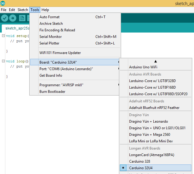
Next, tell the Arduino IDE to use the Carduino. To do this, click Tools > Board > Carduino 32U4 under Longen AVR Boards.
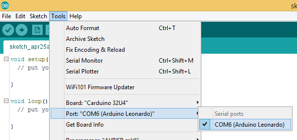
Then select the proper port in Tools > Port > (the Serial/COM port of your Carduino).
Next, upload the program by clicking Sketch > Upload.
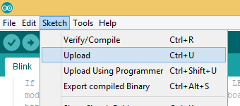
It will take some time to compile and upload the sketch into the Carduino.
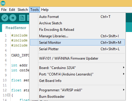
Once uploaded, open the Serial Monitor by clicking Tools > Serial Monitor.
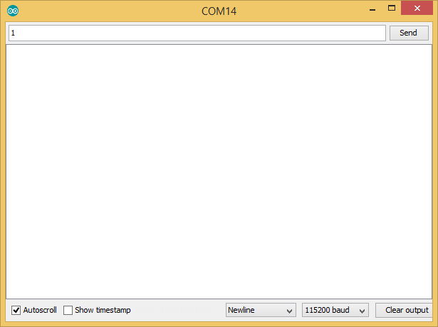
In the Serial Monitor, select 115200 baud from the drop-down list. Then type any number or character (E.g. 1) and click Send button.
First, it will output the device information of your BME280 card such as I2C address, device id, number of sensors, name length, name, SKU, and version. Then it will continually output the temperature, humidity, pressure, and altitude.
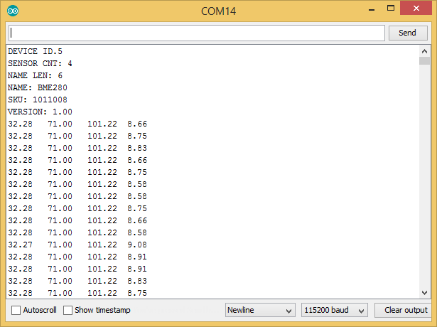
Here is the list of units associated with each sensor reading.
- Temperature - Celsius (°C)
- Humidity - Relative Humidity (RH)
- Pressure - Pascal (Pa)
- Altitude - meter (m)
The blue LED on the ATmega 168PA module will blink quickly and continually during the sensor data reading from Carduino using I2C communication protocol.