Introduction
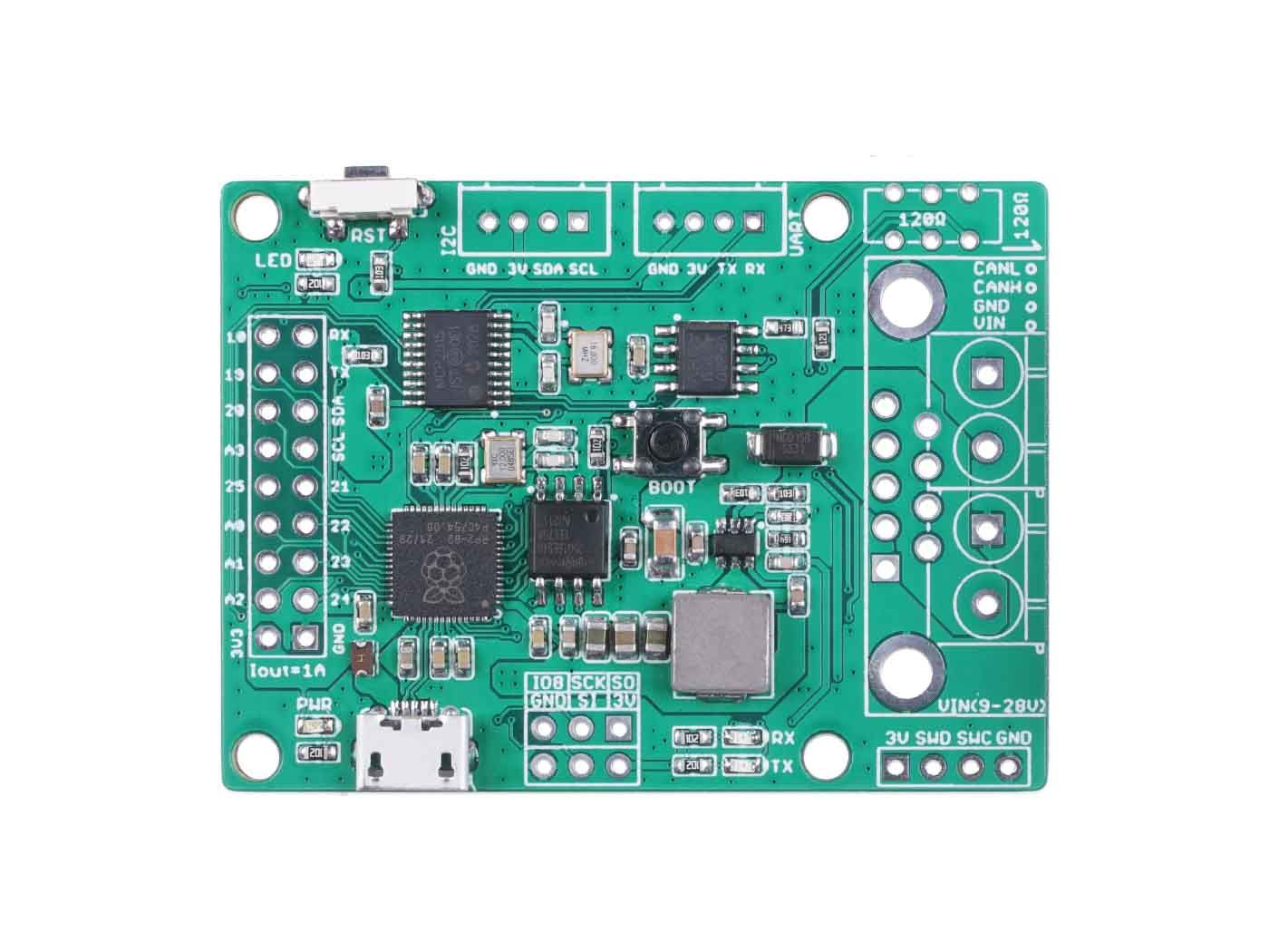
CANBed 2040 is a CAN Bus development board based on RP2040, which has 2MB of Flash and 264KB of RAM. The operating frequency is up to 133MHz, which is suitable for most embedded applications.
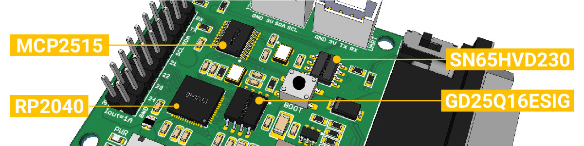
CANBed 2040 uses MCP2515 as CAN controller and MCP2551 as CAN receiver, chich are high-performance CAN Bus chip, work at CAN 2.0 protocols. There is a Micro USB connector on the board, through which you can program the board or supply power to the board. There are one I2C, one UART, one SPI interface, 3 analog input interfaces and 8 digital IO on the board.
We use a flexible way for CAN interface. You can use 4PIN Terminal or DB9 connector. DB9 connector uses OBD-II mode by default. You can also configure CAN Open mode on the hardware. The voltage input range of the CAN interface is 9-28V, which can provide a stable 3.3V/1A output.
If you want to use this board to develop OBD related applications, click to get a DB9 to OBD-II cable.
Note
For transportation considerations, the plug-in components of the kit are not soldered by default. After you receive the kit, you need to do some soldering work. If necessary, you can also contact info@longan-labs.cc after purchasing the board, then we can send it to you after the board is soldered well.
*** Version Track
Version Track
V1.0: Initial version
V1.1:
- Change operate voltage to 3.3V
- Change the DCDC chip to DIO54302
Application Ideas
With CANBed 2040, you can,
- To learn CAN Bus communication
- To build product prototypes. After you complete the product prototype, we can help you integrate it into a product and assist you in production
- To read the data from the car
- As a part of your product, you don't need to design the MCU and CAN Bus separately, only need to complete other hardware design
CANBed Family
Currently we have 6 CANBeds, you can choose the right one according to your needs.
| VRESION | CANBed V1 | CANBed FD | CANBed M0 | CANBed M4 | CANBed RP2040 | CANBed Dual |
|---|---|---|---|---|---|---|
| MCU | Atmega32U4 | Atmega32U4 | ATSAMD21G18 | ATSAME51G19A | RP2040 | RP2040 |
| CORE | AVR 8 bit | AVR 8 bit | ARM Cortex M0+ 32bit | ARM Cortex M4 32bit | Dual ARM Cortex-M0+ | Dual ARM Cortex-M0+ |
| PROTOCOL | CAN2.0 | CANFD & CAN2.0 | CAN2.0 | CANFD & CAN2.0 | CAN2.0 | CANFD & CAN2.0 |
| CLOCK | 16MHz | 16MHz | 48MHz | 133MHz | 133MHz | 133MHz |
| FLASH | 32KB | 32KB | 256KB | 2MKB | 2MKB | 2MKB |
| RAM | 2.5KB | 2.5KB | 32KB | 192KB | 264KB | 264KB |
| PRICE | $24.9 | $29.9 | EoL | $49.9 | $15.9 | $24.9 |
| LINK | GET ONE | GET ONE | GET ONE | GET ONE | GET ONE | GET ONE |
Note
The above price may not be the latest price, please refer to the price on the product page.
CAN BUS PRODUCTS LIST OF LONGAN LABS

We have made a lot of can bus products, you can get more information through the following list, so as to choose a product suitable for you.
| PRODUCT NAME | LINK | PRICE | MCU | CHIP | PROTOCOL |
|---|---|---|---|---|---|
| Serial CAN Bus Module | LINK | $19.9 | ATMEGA168PA | MCP2515 | CAN2.0 |
| I2C CAN Bus Module | LINK | $19.9 | ATMEGA168PA | MCP2515 | CAN2.0 |
| OBD-II Serial CAN Bus Dev Kit | LINK | $20.9 | ATMEGA168PA | MCP2515 | CAN2.0 |
| OBD-II CAN Bus GPS Dev Kit | LINK | $29.9 | ATMEGA32U4 | MCP2515 | CAN2.0 |
| OBD-II CAN Bus Basic Dev Kit | LINK | $24.9 | ATMEGA32U4 | MCP2515 | CAN2.0 |
| CAN-FD Shield | LINK | $19.9 | NO MCU | MCP2517FD | CAN-FD |
| CAN Bus Shield | LINK | $9.9 | NO MCU | MCP2515 | CAN2.0 |
| CANBed | LINK | $24.9 | ATMEGA32U4 | MCP2515 | CAN2.0 |
| CANBed-FD | LINK | $29.9 | ATMEGA32U4 | MCP2517FD | CAN-FD |
| CANBed M4 | LINK | $49.9 | ATSAME51 | - | CAN-FD |
| OBD-II RF Dev Kit | LINK | $19.9 | ATmega168PA | MCP2515 | CAN2.0 |
Note
The above price may not be the latest price, please refer to the price on the product page.
Features
- Powerful RP2040 processor
- CAN V2.0B at up to 1 Mb/s
- Industrial standard 9 pin sub-D connector or 4PIN Terminal.
- OBD-II and CAN standard pinout selectable at sub-D connector
- 2x4Pin Connector compatable with Grove system from Seeedstudio
- SPI Interface
- Standard (11 bit) and extended (29 bit) data and remote frames
- Power input from 9-28V
Specifications
| Parameter | Value |
|---|---|
| MCU | RP2040 |
| Clock Speed | flexible clock running up to 133 MHz |
| Flash Memory | 2MB |
| RAM | 264KB |
| Operate Voltage | 9-28V |
| Output Current @ 3.3V | 1A |
| Input Interface | sub-D |
Hardware Overview
Part List
Note
For transportation considerations, the plug-in components of the kit are not soldered by default. After you receive the kit, you need to do some soldering work. If necessary, you can also contact info@longan-labs.cc after purchasing the board, then we can send it to you after the board is soldered well.
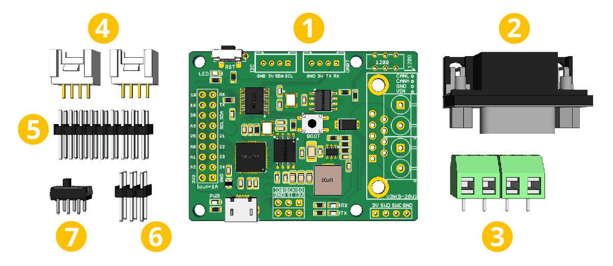
- CANBed RP2040 PCBA
- sub-D connector
- 4PIN Terminal
- 4PIN HY2.0 Connector x 2
- 9x2 2.54 Header x 1
- 3x3 2.54 Header x 1
- Switch for 120Ω terminal resistor
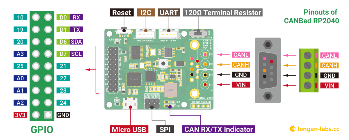
Pin out
Note
Click to get larger image.
1. GPIO - 9x2 I/O Pin OUT:
The I/Os of RP2040 list out here, which is consist of,
- 1 x UART
- 1 x I2C (Wire1)
- 4 x Analog Input(can be used us Digital IO)
- 8 x Digital I/O
2. Micro USB connector for programming
3. SPI Interface
4. CAN RX/TX Indicator
When CAN Bus is transmitting data, these two leds blink.
5. DB9 connector or Terminal for CAN Bus
6. Switch for the 120Ω terminal resistor for CAN Bus

If you use this board on the end of the CAN bus, please put this switch to 120Ω. For more detail about the CAN bus protocol, please refer to the NI CAN Physical Layer and Termination Guide
7. Grove connector for UART
Use Serial1 in the code
8.Grove connector for I2C (Wire1)
9. Reset
Click to reset the board.
DB9 connector
The DB9 interface of CAN Bus has two different protocols, OBD and CAN Open. Their definition is as follows,
| pin# | OBD(default) | CAN OPEN |
|---|---|---|
| 1 | GND | N.C |
| 2 | GND | CAN_L |
| 3 | CANH | GND |
| 4 | N.C | N.C |
| 5 | CANL | GND |
| 6 | N.C | N.C |
| 7 | N.C | CAN_H |
| 8 | N.C | N.C |
| 9 | CAN_V+ | CAN_V+ |
If you want to use the OBD protocol, you don't need to make any changes to the hardware.
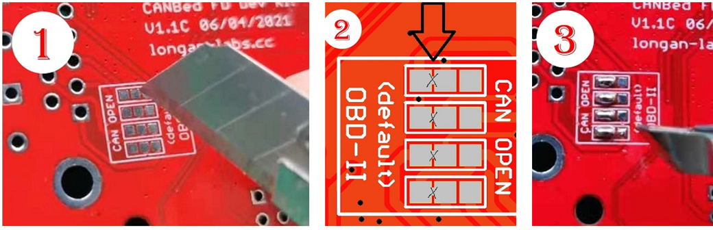
If you need to use the CAN Open protocol, first we look at the back side of the PCB board, you can see the Pads below,
Note
The picture shows another board, but it doesn't matter, the operation method is the same.
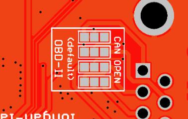
These pads are connected to the OBD side by default. We have to prepare a knife to disconnect the OBD side, and then use an electric soldering iron to solder the CAN Open side of the pads.
Getting Started with Arduino IDE
Here we use the Arduino IDE as a demonstration, through this chapter you can learn how to get started with CANBed 2040. You need a micro USB cable to connect the CANBed RP2040 to the computer.
Arduino IDE Steup
First download the Arduino IDE from https://www.arduino.cc/en/Main/Software. Arduino IDE can be installed and run on Windows, Linux, and Mac OS X operating systems. Download the installer or zip file (Windows only) and install (if you have the zip file, extract it to your Windows computer’s hard drive) it on your operating system.
Once finished, start the Arduino IDE.
Copy and paste the link below into the Additional Boards Manager URLs option in the Arduino IDE preferences (File > Preferences).
https://raw.githubusercontent.com/Longan-Labs/Longan-RP2040/main/package_rp2040_index.json
Once done, click OK button to save the new preference settings.
Now open the Boards Manager by navigating to the Tools -> Board menu.
Select All from the Type drop-down menu. Then type longan in the top search bar. While typing, you will see the Longan RP2040 Boards package.
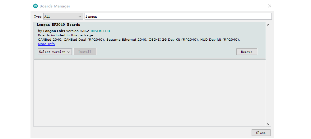
Click on the Longan RP2040 Boards by Longan Labs and then click on Install button.
Once installed, close the Boards Manager window.
Download the install the library
Click to get the Arduino Library for CANBed 2040 Dev board.
In the Arduino IDE, navigate to Sketch > Include Library > Add .ZIP Library to install the Library.
Open the code and upload it to the board
Open the Arduino IDE, here we open the send example. This example can continuously send data to the CAN Bus. Please modify the SPI_CS_PIN to 9 to fit the board.
#include <mcp_can.h>
#include <SPI.h>

/* Please modify SPI_CS_PIN to adapt to different baords.

   CANBed V1        - 17
   CANBed M0        - 3
   CAN Bus Shield   - 9
   CANBed 2040      - 9
   CANBed Dual      - 9
   OBD-2G Dev Kit   - 9
   Hud Dev Kit      - 9
*/

MCP_CAN CAN(SPI_CS_PIN);                                    // Set CS pin

void setup()
{
    Serial.begin(115200);
    while(!Serial);

    // below code need for OBD-II GPS Dev Kit
    // pinMode(A3, OUTPUT);
    // digitalWrite(A3, HIGH);

    while (CAN_OK != CAN.begin(CAN_500KBPS))    // init can bus : baudrate = 500k
    {
        Serial.println("CAN BUS FAIL!");
        delay(100);
    }
    Serial.println("CAN BUS OK!");
}

unsigned char stmp[8] = {0, 1, 2, 3, 4, 5, 6, 7};
void loop()
{
    CAN.sendMsgBuf(0x00, 0, 8, stmp);
    delay(100);                       // send data per 100ms
}

// END FILE
You need to select CANBed 2040 on the Arduino IDE boards and select the correct COM port. Then you can upload the program to the CANBed 2040 Dev board by pressing the Upolading button on Arduino IDE.
Arduino Code
We provide an Arduino library for CANBed 2040.
Note
Please change the SPI_CS_PIN to 9 for CANBed 2040
There're many examples for the library, which is consist of,
- OBDII-PIDs - Get data from OBD-II interface
- send - Send a frame to CAN Bus
- recv - Receive a frame from CAN Bus
- set_mask_filter_recv - Receive a frame from CAN Bus with mask and filter setting
APIs
1. Set the Baud rate
This function is used to initialize the baud rate of the CAN Bus system.
The available baud rates are listed as follows:
#define CAN_5KBPS    1
#define CAN_10KBPS   2
#define CAN_20KBPS   3
#define CAN_25KBPS   4
#define CAN_31K25BPS 5
#define CAN_33KBPS   6
#define CAN_40KBPS   7
#define CAN_50KBPS   8
#define CAN_80KBPS   9
#define CAN_83K3BPS  10
#define CAN_95KBPS   11
#define CAN_100KBPS  12
#define CAN_125KBPS  13
#define CAN_200KBPS  14
#define CAN_250KBPS  15
#define CAN_500KBPS  16
#define CAN_666kbps  17
#define CAN_1000KBPS 18
2. Set Receive Mask and Filter
There are 2 receive mask registers and 5 filter registers on the controller chip that guarantee you getting data from the target device. They are useful especially in a large network consisting of numerous nodes.
We provide two functions for you to utilize these mask and filter registers. They are:
Mask:
init_Mask(unsigned char num, unsigned char ext, unsigned char ulData);
Filter:
init_Filt(unsigned char num, unsigned char ext, unsigned char ulData);
- num represents which register to use. You can fill 0 or 1 for mask and 0 to 5 for filter.
- ext represents the status of the frame. 0 means it's a mask or filter for a standard frame. 1 means it's for a extended frame.
- ulData represents the content of the mask of filter.
3. Check Receive
The MCP2515 can operate in either a polled mode, where the software checks for a received frame, or using additional pins to signal that a frame has been received or transmit completed.
Use the following function to poll for received frames.
INT8U MCP_CAN::checkReceive(void);
The function will return 1 if a frame arrives, and 0 if nothing arrives.
4. Get CAN ID
When some data arrive, you can use the following function to get the CAN ID of the "send" node.
INT32U MCP_CAN::getCanId(void)
5. Send a frame
CAN.sendMsgBuf(INT8U id, INT8U ext, INT8U len, data_buf);
It is a function to send data onto the bus. In which:
- id ID of can frame.
- ext represents the status of the frame. '0' means standard frame. '1' means extended frame.
- len represents the length of this frame.
- data_buf is the content of this message.
For example, In the 'send' example, we have:
unsigned char stmp[8] = {0, 1, 2, 3, 4, 5, 6, 7};
CAN.sendMsgBuf(0x00, 0, 8, stmp); //send out the message 'stmp' to the bus and tell other devices this is a standard frame from 0x00.
6. Receive a frame
The following function is used to receive data on the 'receive' node:
CAN.readMsgBuf(unsigned char len, unsigned char buf);
In conditions that masks and filters have been set. This function can only get frames that meet the requirements of masks and filters.
- len represents the data length.
- buf is where you store the data.
Get data from a Vehicle
We can use CANBed RP2040 to get data from a vehicle, we take the vehicle speed for an example here.
You can use our products to read data from cars. Here we provide a simple example by which you can read the speed and revs from a car. This is the OBD-based PIDs protocol. Regarding the deeper technology of OBD, we can't provide support at present. You may need to have some understanding of the car's protocol. After all, we are more of a hardware supplier.
The interface of OBD is as follows,
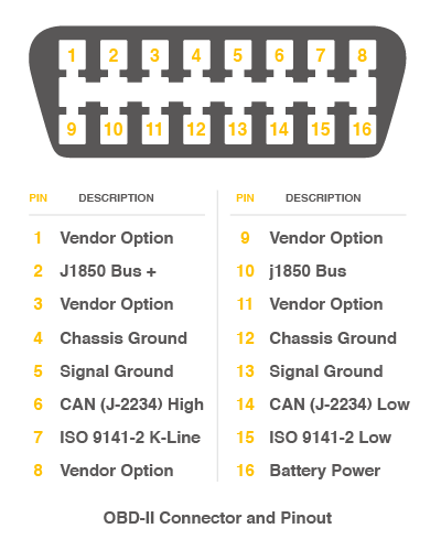
There're 4 pins we need to connect.
| OBD Pin | CANBed PIN |
|---|---|
| 5. Signal Ground | GND |
| 6. CAN(J-2234) High | CANH |
| 14. CAN(J-2234) Low | CANL |
| 16. Battery Power | VIN |
You can also use our OBD-II to DB9 Cable, which is very convenient to connect to OBD.
Upload the following code to the development board, then open the serial monitor, you get the speed from the car now.
#include <SPI.h>
#include "mcp_can.h"

/* Please modify SPI_CS_PIN to adapt to different baords.

   CANBed V1        - 17
   CANBed M0        - 3
   CAN Bus Shield   - 9
   CANBed 2040      - 9
   CANBed Dual      - 9
   OBD-2G Dev Kit   - 9
   Hud Dev Kit      - 9
*/

#define SPI_CS_PIN  9

MCP_CAN CAN(SPI_CS_PIN);                                    // Set CS pin

#define PID_ENGIN_PRM       0x0C
#define PID_VEHICLE_SPEED   0x0D
#define PID_COOLANT_TEMP    0x05

#define CAN_ID_PID          0x7DF

void set_mask_filt()
{
    // set mask, set both the mask to 0x3ff

    CAN.init_Mask(0, 0, 0x7FC);
    CAN.init_Mask(1, 0, 0x7FC);

    // set filter, we can receive id from 0x04 ~ 0x09

    CAN.init_Filt(0, 0, 0x7E8);
    CAN.init_Filt(1, 0, 0x7E8);

    CAN.init_Filt(2, 0, 0x7E8);
    CAN.init_Filt(3, 0, 0x7E8);
    CAN.init_Filt(4, 0, 0x7E8);
    CAN.init_Filt(5, 0, 0x7E8);
}

void sendPid(unsigned char __pid) {
    unsigned char tmp[8] = {0x02, 0x01, __pid, 0, 0, 0, 0, 0};
    CAN.sendMsgBuf(CAN_ID_PID, 0, 8, tmp);
}

bool getSpeed(int *s)
{
    sendPid(PID_VEHICLE_SPEED);
    unsigned long __timeout = millis();

    while(millis()-__timeout < 1000)      // 1s time out
    {
        unsigned char len = 0;
        unsigned char buf[8];

        if (CAN_MSGAVAIL == CAN.checkReceive()) {                // check if get data
            CAN.readMsgBuf(&len, buf);    // read data,  len: data length, buf: data buf

            if(buf[1] == 0x41)
            {
                *s = buf[3];
                return 1;
            }
        }
    }

    return 0;
}

void setup() {
    Serial.begin(115200);
    while(!Serial);

    // below code need for OBD-II GPS Dev Kit
    // pinMode(A3, OUTPUT);
    // digitalWrite(A3, HIGH);

    while (CAN_OK != CAN.begin(CAN_500KBPS)) {             // init can bus : baudrate = 500k
        Serial.println("CAN init fail, retry...");
        delay(100);
    }
    Serial.println("CAN init ok!");
    set_mask_filt();
}

void loop() {

    int __speed = 0;
    int ret = getSpeed(&__speed);
    if(ret)
    {
        Serial.print("Vehicle Speed: ");
        Serial.print(__speed);
        Serial.println(" kmh");
    }
    delay(500);
}

// END FILE
Getting Started with MicroPython
What is MicroPython
MicroPython is a Python interpreter (with partial native code compilation feature). It provides a subset of Python 3.5 features, implemented for embedded processors and constrained systems. Read more about the differences to CPython here.
![]()
How to Use
As the CANBed 2040 uses the same chip as the Raspberry Pi Pico (RP2040), please to to Getting Started with Pico for details.
FAQ
I can't upload code to CANBed 2040
- When the board is connected to the computer via the Micro USB cable, a new COM device will appear on the computer. If the new device does not appear on your computer, you can try a different USB cable or try another computer.
The RX/TX led light up and never turn off
- Check if the baudrate of CAN Bus is setting correct
- Try turning on/off the switch for the 120Ω terminal resistor
- Check if CANH and CANL is well connected, H to H and L to L
I2C is not working
- There are 2 I2C for RP2040, for this CANBed 2040, we use Wire1, that is, please change Wire to Wire1
- And before Wire1.begin(), plese add Wire1.setSDA(6) and Wire1.setSCL(7) to select the pin.
How to find the tech support
Please contact support@longan-labs.cc for technical support. Our technical support engineer will usually reply you within 24 hours on working days. In order to get faster support, we hope that when you send us an email, you need to include at least the following content,
- When and how to buy the product
- Product version information
- Take a high-definition picture of the product you use, including the connection
- Describe in detail the problem you encountered and what kind of help you would like to get