OBD-II CAN-BUS DEV KIT
Introduction
This kit allows you to interface with your vehicle's OBD-II interface. The kit includes a Serial CAN Bus module as well as a OBD-II Connector, with this kit you can get data from your vehicle easily. We provide an tutorial which is based on Arduino.
OBD-II (short for On-Board Diagnostics, Second Generation) is a set of standards for implementing a computer based system to control emissions from vehicles. It was first introduced in the United States in 1994, and became a requirement on all 1996 and newer US vehicles. Other countries, including Canada, parts of the European Union, Japan, Australia, and Brazil adopted similar legislation. A large portion of the modern vehicle fleet supports OBD-II or one of its regional flavors.
CAN BUS PRODUCTS LIST OF LONGAN LABS

We have made a lot of can bus products, you can get more information through the following list, so as to choose a product suitable for you.
| PRODUCT NAME | LINK | PRICE | MCU | CHIP | PROTOCOL |
|---|---|---|---|---|---|
| Serial CAN Bus Module | LINK | $19.9 | ATMEGA168PA | MCP2515 | CAN2.0 |
| I2C CAN Bus Module | LINK | $19.9 | ATMEGA168PA | MCP2515 | CAN2.0 |
| OBD-II Serial CAN Bus Dev Kit | LINK | $20.9 | ATMEGA168PA | MCP2515 | CAN2.0 |
| OBD-II CAN Bus GPS Dev Kit | LINK | $29.9 | ATMEGA32U4 | MCP2515 | CAN2.0 |
| OBD-II CAN Bus Basic Dev Kit | LINK | $24.9 | ATMEGA32U4 | MCP2515 | CAN2.0 |
| CAN-FD Shield | LINK | $19.9 | NO MCU | MCP2517FD | CAN-FD |
| CAN Bus Shield | LINK | $9.9 | NO MCU | MCP2515 | CAN2.0 |
| CANBed | LINK | $24.9 | ATMEGA32U4 | MCP2515 | CAN2.0 |
| CANBed-FD | LINK | $29.9 | ATMEGA32U4 | MCP2517FD | CAN-FD |
| CANBed M4 | LINK | $49.9 | ATSAME51 | - | CAN-FD |
| OBD-II RF Dev Kit | LINK | $19.9 | ATmega168PA | MCP2515 | CAN2.0 |
Note
The above price may not be the latest price, please refer to the price on the product page.
Features
- Up to 1Mb/s CAN Bus rate
- DIY kit
- Multi-platform avaiable (Arduino, Raspberry, Beaglebone Board, etc.)
- Serial Communication
- Tutorial for Arduino
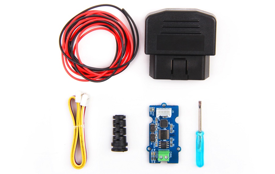
Partlist
- Serial CAN Bus Module
- OBD-II Connector
- Screw Driver
- Cable for CAN Bus
- Grove Cable
Note
The kit don't include a controller board.
Hardware Overview of Serial CAN Bus Module
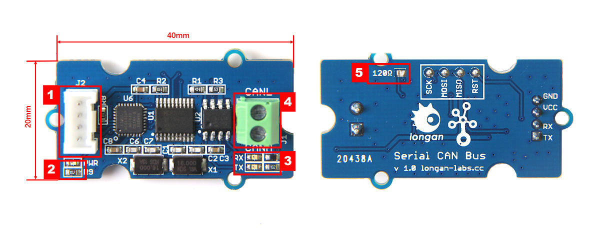
- 4 pin 2.0mm Grove Connector
- Power and status led indicator
- Send and Recv led indicator
- 3.5mm terminal to connect to CAN Bus (CAN_H & CAN_L)
- 120Ω registor, default connected, if you don't need you cut this pad with a box cutter.
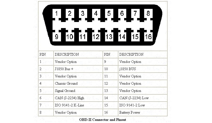
Hardware Connection
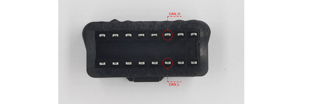
The kit includes an OBD-II connector, below is pins define of the connector.
The kit includes a cable as well, you need a soldering iron to connect the cable to the connector. As shown below.
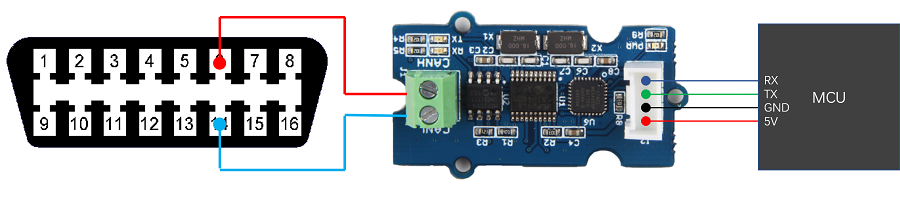
The OBD-II connect wired as below:
Getting Started with Arduino
Here we will make a demo to read some value from a vehicle with an Arduino.
Download Arduino library of the board from Github
Open the example "obd_demo".
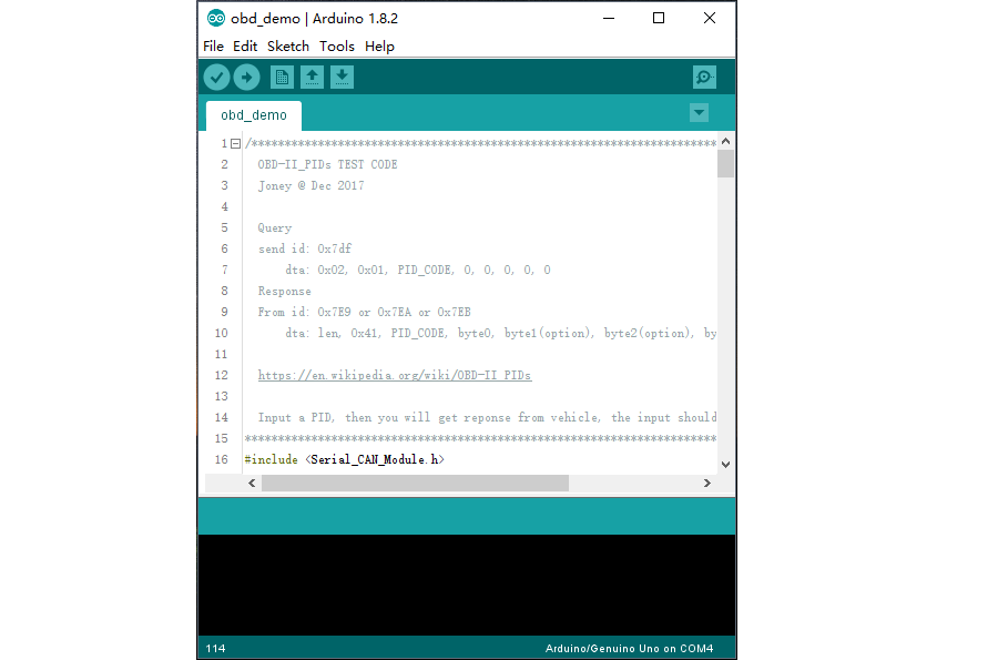
For this example, we use D2 as RX of software serial, D3 as TX. So you should connect D2 to TX of Serial can bus module, and D3 to RX.
After upload the sketch to Arduino, you can try connect OBD-II connector to your vehicle.
Open you serial monitor, try to input an OBD-PIDs, see if you can get some values from your vehicle.
Click to get more about OBD-PIDs.