Temperature Card
Introduction
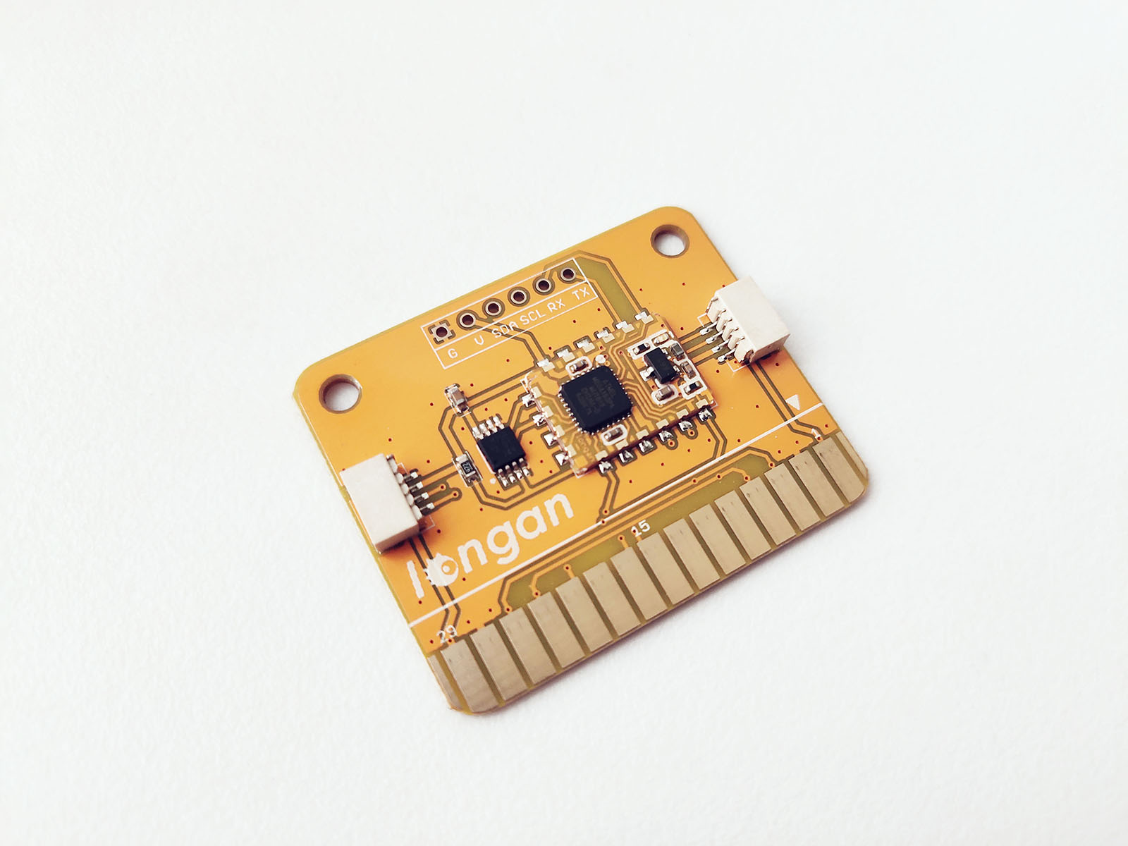
The temperature card features LM75A which is a temperature-to-digital converter using an on-chip band gap temperature sensor and Sigma-delta A-to-D conversion technique. It supports two wire I2C bus interface. The front of the temperature card has following components.
- LM75A digital temperature sensor
- Gold fingers (edge connector)
- Connectors
- Module card
- LED indicator
Specifications
- Voltage: 5V
- Resolution: 0.125 degrees
- Temperature Range: -55° C to 125° C
- Supports two wire I2C bus interface
- Error of ± 3 ° C
I2C Address
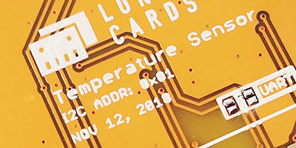
The Temperature card at the factory default I2C address of 0x01. The factory default I2C address is printed on the back of the card.
Pins
The edge connector (gold fingers) has total of 30 contacts (each side has 15 contacts).
On the front side of the temperature card, a white arrow is printed near the edge connector indicates the pin #1. You can find some pin numbers printed on the edge connector itself (1, 15, and 29). You can count the pin numbers starting with 1 and count by twos from right to left would be 1, 3, 7, 9, 11, 15, 17, 19, 21, 23, 27, and 29. Notice that all the counts are odd numbers.
On the back side of the temperature card, you also can find some pin numbers printed on the edge connector itself (2, 16, and 30). You can count the pin numbers starting with 2 and count by twos from left to right would be 2, 4, 6, 8, 10, 12, 14, 16, 18, 20, 22, 24, 26, 28 and 30. Notice that all the counts are even numbers.
I2C
Following pins can be used for I2C communication.
- SDA: Digital I/O, I2C bus serial bidirectional data line (Front: pin #5, #25 / Back: pin #6, #26)
- SCL: Digital Input, I2C bus serial clock input (Front: pin #7, #23 / Back: pin #8, #24)
Power
Following pins connect with the common power bus of the board.
- VCC: Power supply (Front: pin #1, #29 / Back: pin #2, #30)
- GND: To be connected to the system ground (Front: pin #3, #27 / Back: pin #4, #28)
I2C Bus and UART Test Point
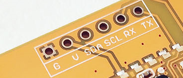
You can solder a break away header (straight, 0.1” pin spacing) to the I2C bus test point. The I2C bus requires two wires to communicate with the device, a serial data line (SDA) and a serial clock line (SCL). There is an additional RX, TX, VCC, and GND that is not part of the I2C interface.
How to Use
The temperature card can be plugged into an edge connector slot of one of the following Longan boards.
- Game board
- Car board
- Sensor board
- Extension board
- Pi Hap
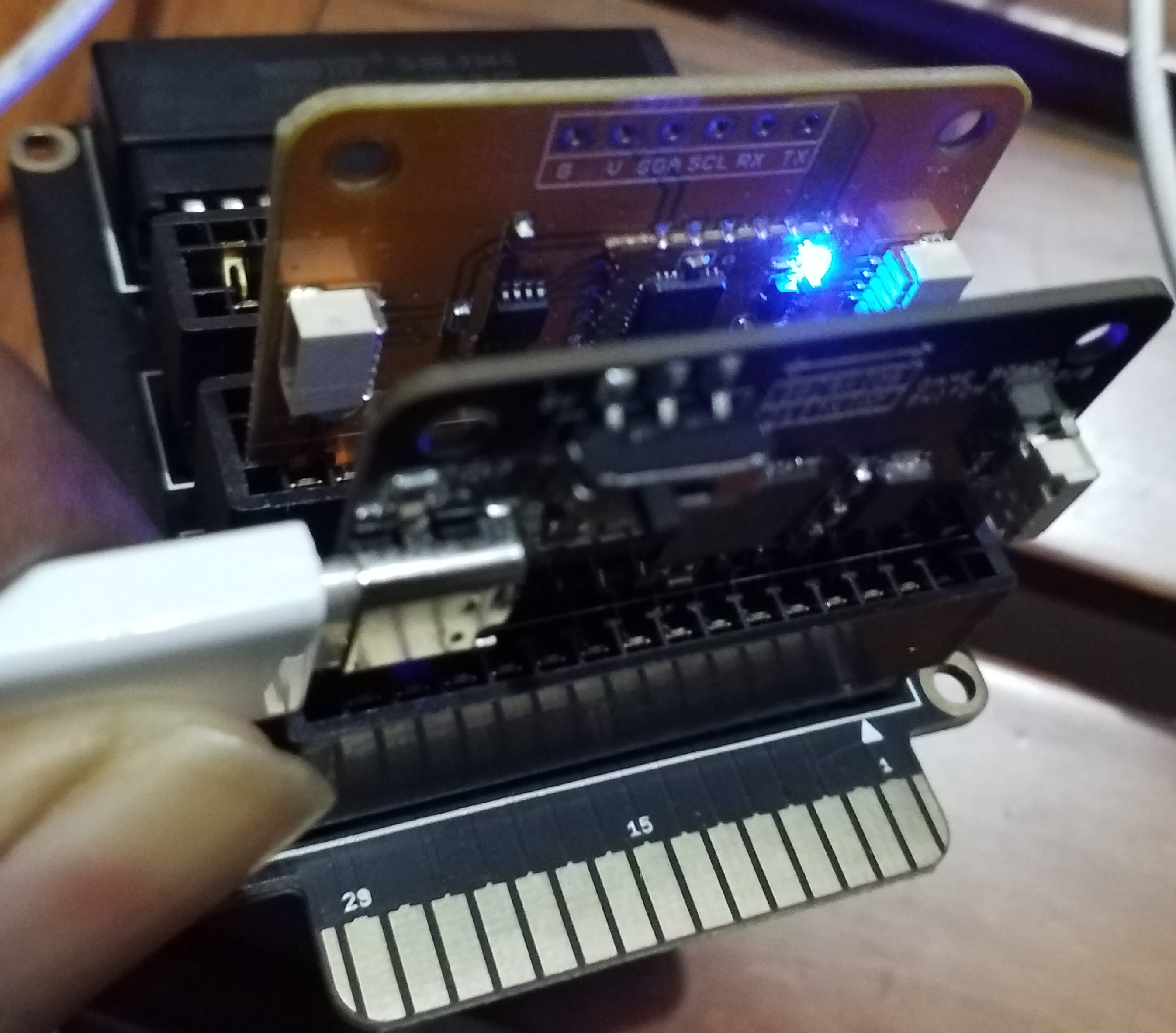
When you plugging, the white arrow head printed on the card should be pointing toward the white arrow head printed near the edge connector slot of the board. Once plugged, it can communicate with the Carduino through the I2C bus line of the board. It will also connect to the common power bus of the board.
Getting Ready
You can use the extension board to connect any Longan card with the Carduino.
-
First take the Extension board.
-
Next, plug the temperature card in to one of the edge connector slot.
-
Then plug the Carduino in to another edge connector slot.
-
Finally, connect the extension board with your computer using a Type-C USB cable (you can use either USB connector on the Carduino or the Extension board).
Reading Temperature
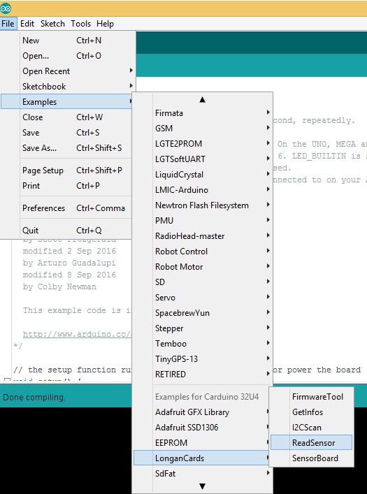
The sample code can be loaded to your Arduino IDE by clicking on File > Examples > LonganCards > ReadSensor.
If you have trouble loading the ReadSensor sketch from the examples, you can copy and paste the code below into the Arduino editor.
#include <Wire.h>
#include "CardsDfs.h"
#include "LonganCards.h"

CARD_INFO card;

int addr = 0;
int cntSensor = 0;

float sensorValue[10];

float str2num(unsigned char *str)
{
    float num = 0;
    memcpy((unsigned char *)(&num), str, 4);
    return num;
}

void setup() {
    // put your setup code here, to run once:
    Serial.begin(115200);
    Wire.begin();

    while(!Serial.available());

    addr = card.scan();
    if(0 == addr)
    {
        Serial.println("NO DEVICE!");
        while(1);
    }

    card.getInfo();
    card.disp();

    cntSensor = card.senCnt;
}

void loop()
{
    for(int i=0; i<cntSensor; i++)
    {
        sensorValue[i] = getValue(i);
        Serial.print(sensorValue[i], 2);
        Serial.print('\t');
    }

    Serial.println();
    delay(100);
}

float getValue(int s)
{
    unsigned char dta[10];
    unsigned long len = 0;

    Wire.beginTransmission(addr);
    Wire.write(REG_VALUE_START+s);      // ADDR_DATA_START = 0x30
    Wire.endTransmission();

    delay(1);
    Wire.requestFrom(addr, 6);

    delay(1);

    while(Wire.available())
    {
        dta[len++] = Wire.read();
    }

    return str2num(&dta[1]);
}

// END FILE
Connect the Type-C USB cable to the USB connector of the Carduino and connect the other end to your computer.
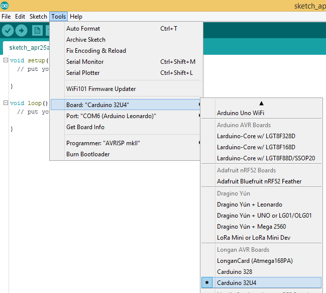
Next, tell the Arduino IDE to use the Carduino. To do this, click Tools > Board > Carduino 32U4 under Longen AVR Boards.
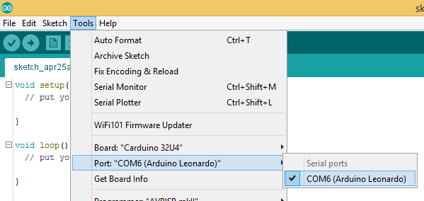
Then select the proper port in Tools > Port > (the Serial/COM port of your Carduino).
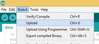
Next, upload the program by clicking Sketch > Upload.
It will take some time to compile and upload the sketch into the Carduino.
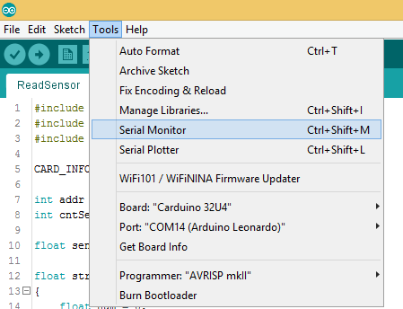
Once uploaded, open the Serial Monitor by clicking Tools > Serial Monitor.
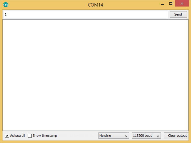
In the Serial Monitor, select 115200 baud from the drop-down list. Then type any number or character (E.g. 1) and click Send button.
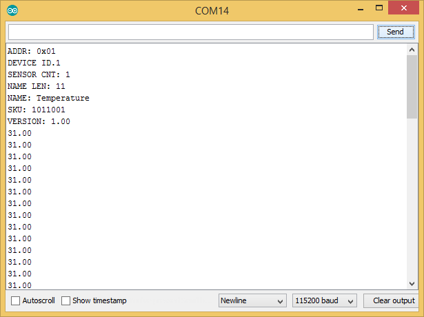
First, it will output the device information of your temperature card such as I2C address, device id, number of sensors, name length, name, SKU, and version. Then it will continually output the temperature.
The blue LED on the ATmega 168P module will blink quickly and continually during the temperature reading from Carduino using I2C communication protocol.