1030011
Introduction
The Serial CAN Lite Module provide your Arduino or others MCU with the capability to communication to CAN Bus, such as hacking your vehicle. CAN Bus is a common industrial bus because of its long travel distance, medium communication speed and high reliability.
This Serial CAN Bus module is based on MCP2551 and MCP2515, which can provide speed up to 1Mb/s.
This module the is a cheaper version of Serial CAN Bus Module, the difference is the MCU on-board. Lite version user a cheaper STM8S MCU while there's Atmega168PA in the Serial CAN Bus Module. The 2 modules shares the same AT command and usage.
If you need to program the AVR mcu with Arduino IDE, please take Serial CAN Bus module, otherwise, the Lite version is good enough.
CAN BUS PRODUCTS LIST OF LONGAN LABS

We have made a lot of can bus products, you can get more information through the following list, so as to choose a product suitable for you.
| PRODUCT NAME | LINK | PRICE | MCU | CHIP | PROTOCOL |
|---|---|---|---|---|---|
| Serial CAN Bus Module | LINK | $19.9 | ATMEGA168PA | MCP2515 | CAN2.0 |
| I2C CAN Bus Module | LINK | $19.9 | ATMEGA168PA | MCP2515 | CAN2.0 |
| OBD-II Serial CAN Bus Dev Kit | LINK | $20.9 | ATMEGA168PA | MCP2515 | CAN2.0 |
| OBD-II CAN Bus GPS Dev Kit | LINK | $29.9 | ATMEGA32U4 | MCP2515 | CAN2.0 |
| OBD-II CAN Bus Basic Dev Kit | LINK | $24.9 | ATMEGA32U4 | MCP2515 | CAN2.0 |
| CAN-FD Shield | LINK | $19.9 | NO MCU | MCP2517FD | CAN-FD |
| CAN Bus Shield | LINK | $9.9 | NO MCU | MCP2515 | CAN2.0 |
| CANBed | LINK | $24.9 | ATMEGA32U4 | MCP2515 | CAN2.0 |
| CANBed-FD | LINK | $29.9 | ATMEGA32U4 | MCP2517FD | CAN-FD |
| CANBed M4 | LINK | $49.9 | ATSAME51 | - | CAN-FD |
| OBD-II RF Dev Kit | LINK | $19.9 | ATmega168PA | MCP2515 | CAN2.0 |
Note
The above price may not be the latest price, please refer to the price on the product page.
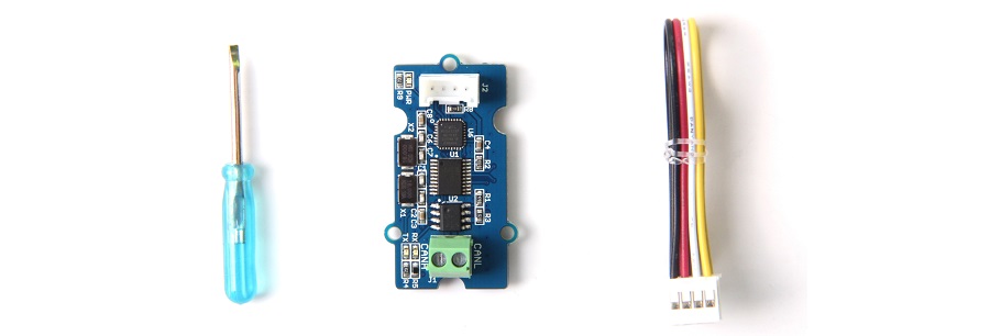
Partlist
Features
- Uart to CAN Bus communication
- Work with Arduino/BeagleBone board/Pi or any MCU that integrated with Uart.
- AT command
- Up to 115200 Uart baud rate (default 9600)
- Up to 1Mb/s CAN Bus baud rate
- TX and RX led indicator
- 4pin Grove connector
- 3.3 / 5V working voltage
- Easy-to-use Arduino library
- Small size: 20x40 mm
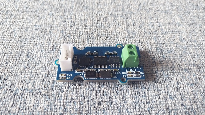
Hardware Overview
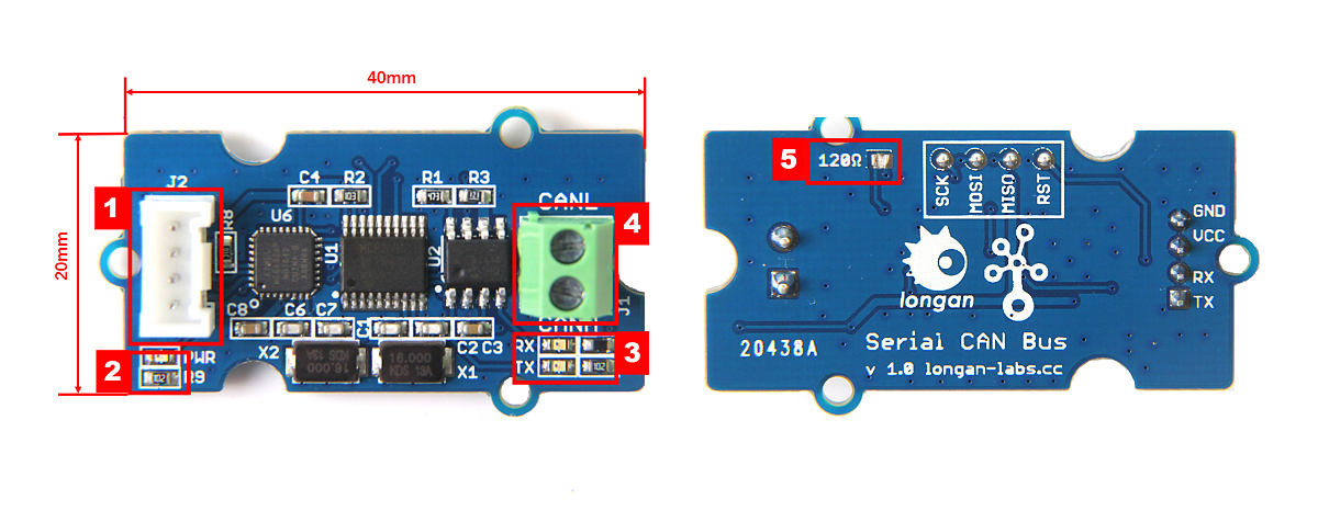
- 4 pin 2.0mm Grove Connector
- Power and status led indicator
- Send and Recv led indicator
- 3.5mm terminal to connect to CAN Bus (CAN_H & CAN_L)
- 120Ω registor.
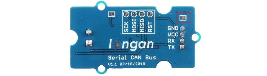
Work at 3.3V
The module is working at 5V most of time. If you want it to work at 3.3V IO, please try:
There's a jumper on the back side, please connect the pads together with a soldering iron. And VCC must connect to 5V.
AT Command
You can achieve the complete function of this Serial CAN Bus module with only a few AT command.
| CMD | Description |
|---|---|
| +++ | Switch from Normal mode to Config mode |
| AT+S=[value] | Set serial baud rate |
| AT+C=[value] | Set CAN Bus baud rate |
| AT+M=[N][EXT][value] | Set mask |
| AT+F=[N][EXT][value] | Set filter |
| AT+Q | Switch to Normal Mode |
Note
All of the cmd should end with '\n' except +++
Set Serial Baud Rate
You can set the serial baud rate of the module with this command. There're 5 rates available, up to 115200 b/s.
AT+S=[value]
| value | 0 | 1 | 2 | 3 | 4 |
|---|---|---|---|---|---|
| baud rate(b/s) | 9600 | 19200 | 38400 | 57600 | 115200 |
Note
Default is 9600
Eg: Set serial baud rate to 57600
AT+S=3
Respose
OK or ERROR
Set CAN Bus Baudrate
You can use this command to set the rate of CAN Bus, there's 18 rates available. Normally, if you want to hack your vehicle, 500k is the right one.
AT+C=[value]
| value | 01 | 02 | 03 | 04 | 05 | 06 | 07 | 08 | 09 | 10 | 11 | 12 | 13 | 14 | 15 | 16 | 17 | 18 |
|---|---|---|---|---|---|---|---|---|---|---|---|---|---|---|---|---|---|---|
| rate(kb/s) | 5 | 10 | 20 | 25 | 31.2 | 33 | 40 | 50 | 80 | 83.3 | 95 | 100 | 125 | 200 | 250 | 500 | 666 | 1000 |
Tip
Default is 500K
Eg: Set CAN BUS baud rate to 50K
AT+C=08
Respose
OK or ERROR
Set Mask
There're 2 Mask for the module, Mask0 and Mask1.
AT+M=[N][EXT][value]
N:
- 0: Mask0
- 1: Mask1
EXT:
- 0: Standard Frame
- 1: Extended Frame
value:
Neeed 8 bit of character, hexadecimal.
Eg: Set Mask1 to 0x3DF, standard frame:
AT+M=[1][0][000003DF]
Respose
OK or ERROR
Set Filt
There're 6 Mask for the module, Filt0 ~ Filt5
AT+F=[N][EXT][value]
N:
| N | 0 | 1 | 2 | 3 | 4 | 5 |
|---|---|---|---|---|---|---|
| Filt | Filt0 | Filt1 | Filt2 | Filt3 | Filt4 | Filt5 |
EXT:
- 0: Standard Frame
- 1: Extended Frame
value:
Neeed 8 bit of character, hexadecimal.
Eg: Set Filt3 to 0x2C, standard frame:
AT+F=[1][0][0000002C]
Respose
OK or ERROR
Normal Mode
When the module working on Normal mode, you can send and recevie data from CAN Bus.
Send
You should send 14 byte of data per frame. Define as below,
| bit | 0 | 1 | 2 | 3 | 4 | 5 | 6 | 7 | 8 | 9 | 10 | 11 | 12 | 13 |
|---|---|---|---|---|---|---|---|---|---|---|---|---|---|---|
| define | ID3 | ID2 | ID1 | ID0 | EXT | RTR | DTA0 | DTA1 | DTA2 | DTA3 | DTA4 | DTA5 | DTA6 | DTA7 |
- ID0~ID3: CAN ID
- EXT: 0 for standard frame, 1 for extended frame
- RTR: 0 for standard frame, 1 for remote frame
- DTA0~DTA7: 8 byte of data
Eg.
Send {1, 2, 3, 4, 5, 6, 7, 8} to ID:0x3DC, Standard frame:
{0, 0, 3, 0xDC, 0, 0, 1, 2, 3, 4, 5, 6, 7, 8}
Recv
You will get 12 byte of data per frame. Define as below,
| bit | 0 | 1 | 2 | 3 | 4 | 5 | 6 | 7 | 8 | 9 | 10 | 11 |
|---|---|---|---|---|---|---|---|---|---|---|---|---|
| define | ID3 | ID2 | ID1 | ID0 | DTA0 | DTA1 | DTA2 | DTA3 | DTA4 | DTA5 | DTA6 | DTA7 |
- ID0~ID3: CAN ID
- DTA0~DTA7: 8 byte of data
Arduino Library
We provide an library for Aruino Software Serial.
Please download it at Github
There're many examples for the library, which is consist of,
- send - How to send a frame to CAN Bus
- recv - How to recv a frame from CAN Bus
- debug - debug mode, you can send a cmd to the module
- set_can_baudrate - set can bus baudrate
- set_mask_filt - set mask and filt of the module